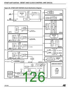
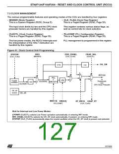
ST92F124/F150/F250 - RESET AND CLOCK CONTROL UNIT (RCCU)
CLOCK MANAGEMENT (Cont’d)
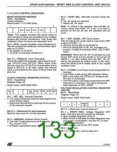
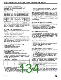
7.3.6 Interrupt Generation
– when the system clock restarts after a hardware
stop (when the STOP MODE feature is availa-
ble on the specific device).
System clock selection modifies the CLKCTL and
CLK_FLAG registers.
– when the PLL loses the programmed frequency
in which it was locked, and when it re-locks
The clock control unit generates an external inter-
rupt request (INTD0) in the following conditions:
This interrupt can be masked by resetting the
INT_SEL bit in the CLKCTL register. Note that this
is the only case in the ST9 where an interrupt is
generated with a high to low transition.
– when CK_AF and CLOCK2/16 are selected or
deselected as system clock source,
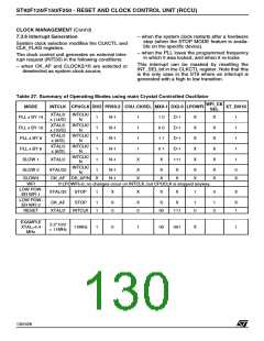
Table 27. Summary of Operating Modes using main Crystal Controlled Oscillator
WFI_CK
SEL
MODE
PLL x BY 14
PLL x BY 10
PLL x BY 8
PLL x BY 6
SLOW 1
INTCLK CPUCLK DIV2 PRS0-2 CSU_CKSEL MX0-1 DX2-0 LPOWFI
XT_DIV16
XTAL/2
x (14/D)
INTCLK/
N
1
1
1
1
1
N-1
N-1
N-1
N-1
N-1
1
1
1
1
X
1 0
0 0
1 1
0 1
X
D-1
D-1
D-1
D-1
111
X
X
X
X
X
X
X
X
X
X
1
1
1
1
1
XTAL/2
x (10/D)
INTCLK/
N
XTAL/2
x (8/D)
INTCLK/
N
XTAL/2
x (6/D)
INTCLK/
N
INTCLK/
N
XTAL/2
INTCLK/
N
SLOW 2
XTAL/32
1
N-1
N-1
X
X
X
X
X
X
X
X
X
X
0
SLOW3
WFI
CK_AF CK_AF/N
X
X
If LPOWFI=0, no changes occur on INTCLK, but CPUCLK is stopped anyway.
LOW POW-
ER WFI 1
XTAL/32
STOP
1
X
X
X
X
1
0
X
LOW POW-
ER WFI 2
CK_AF
XTAL/2
STOP
1
1
X
0
X
0
X
X
1
0
1
0
X
1
RESET
INTCLK
00
111
EXAMPLE
XTAL=4.4
MHz
2.2*10/2
= 11MHz
11MHz
1
0
1
00
001
X
1
130/426
9

 STMICROELECTRONICS [ ST ]