ST92F124/F150/F250 - RESET AND CLOCK CONTROL UNIT (RCCU)
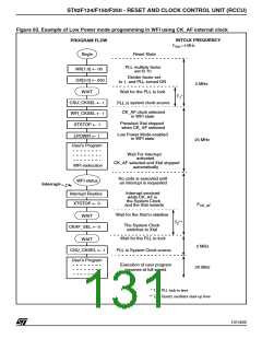
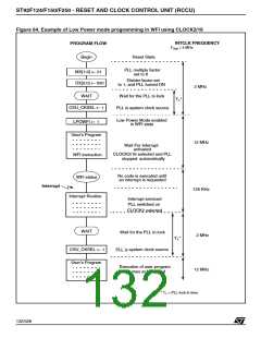
Figure 64. Example of Low Power mode programming in WFI using CLOCK2/16
INTCLK FREQUENCY
Xtal
PROGRAM FLOW
F
= 4 MHz
Begin
Reset State
PLL multiply factor
set to 6
MX[1:0] ← 01
DX[2:0] ← 000
Divider factor set
to 1, and PLL turned ON
2 MHz
Wait for the PLL to lock
WAIT
T *
1
CSU_CKSEL ←
system clock source
PLL is
1
Low Power Mode enabled
in WFI state
LPOWFI ← 1
User’s Program
12 MHz
Wait For Interrupt
activated
CLOCK2/16 selected and PLL
automatically
WFI instruction
stopped
No code is executed until
an interrupt is requested
WFI status
Interrupt
125 KHz
Interrupt Routine
Interrupt serviced
PLL switched on
CLOCK2 selected
WAIT
Wait for the PLL to lock
2 MHz
T *
1
system clock source
PLL is
CSU_CKSEL ← 1
User’s Program
Execution of user program
resumes at full speed
12 MHz
* T = PLL lock-in time
1
132/426
9

 STMICROELECTRONICS [ ST ]