ST92F124/F150/F250 - RESET AND CLOCK CONTROL UNIT (RCCU)
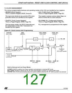
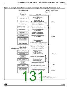
Figure 63. Example of Low Power mode programming in WFI using CK_AF external clock
INTCLK FREQUENCY
PROGRAM FLOW
F
= 4 MHz
Xtal
Begin
Reset State
PLL multiply factor
set to 10
MX[1:0] ← 00
DX[2:0] ← 000
WAIT
Divider factor set
to 1, and PLL turned ON
2 MHz
Wait for the PLL to lock
T *
1
CSU_CKSEL ←
system clock source
PLL is
1
CK_AF clock selected
in WFI state
WFI_CKSEL ← 1
XTSTOP ← 1
Preselect Xtal stopped
when CK_AF selected
Low Power Mode enabled
in WFI state
LPOWFI ← 1
20 MHz
User’s Program
Wait For Interrupt
activated
CK_AF selected and Xtal stopped
WFI instruction
WFI status
automatically
No code is executed until
an interrupt is requested
Interrupt
Interrupt serviced
while CK_AF is
the System Clock
and the Xtal restarts
Interrupt Routine
XTSTOP ← 0
F
CK_AF
Wait for the Xtal to stabilise
WAIT
T **
2
The System Clock
switches to Xtal
CKAF_SEL ← 0
Wait for the PLL to lock
WAIT
2 MHz
CSU_CKSEL ← 1
PLL is
System Clock source
User’s Program
Execution of user program
resumes at full speed
20 MHz
* T = PLL lock-in time
1
** T = Quartz oscillator start-up time
2
131/426
9

 STMICROELECTRONICS [ ST ]