ST92F124/F150/F250 - RESET AND CLOCK CONTROL UNIT (RCCU)
7.3 CLOCK MANAGEMENT
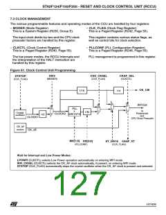
The various programmable features and operating modes of the CCU are handled by four registers:
– MODER (Mode Register)
This is a System Register (R235, Group E).
– CLK_FLAG (Clock Flag Register)
This is a Paged Register (R242, Page 55).
The input clock divide-by-two and the CPU clock
prescaler factors are handled by this register.
This register contains various status flags, as
well as control bits for clock selection.
– CLKCTL (Clock Control Register)
This is a Paged Register (R240, Page 55).
– PLLCONF (PLL Configuration Register)
This is a Paged Register (R246, Page 55).
The low power modes, the RCCU interrupts and
the interpretation of the HALT instruction are
handled by this register.
PLL management is programmed in this register.
Figure 61. Clock Control Unit Programming
DIV2
(MODER)
CSU_CKSEL
(CLK_FLAG)
CKAF_SEL
(CLKCTL)
XTSTOP
(CLK_FLAG)
CK_128
1/16
1/4
0
1
INTCLK
0
1
0
1
0
PLL
x
6/8/10/14
to
Peripherals
and
1/N
Crystal
oscillator
1
CLOCK2
1/2
CLOCK1
CK_AF
CPU Clock Prescaler
CK_AF
source
MX[1:0]
DX[2:0]
XT_DIV16
CKAF_ST
(PLLCONF)
(CLK_FLAG)
Wait for Interrupt and Low Power Modes:
LPOWFI (CLKCTL) selects Low Power operation automatically on entering WFI mode.
WFI_CKSEL (CLKCTL) selects the CK_AF clock automatically, if present, on entering WFI mode.
XTSTOP (CLK_FLAG) automatically stops the crystal oscillator when the CK_AF clock is present and selected.
127/426
9

 STMICROELECTRONICS [ ST ]