ST92F124/F150/F250 - ON-CHIP DIRECT MEMORY ACCESS (DMA)
DMA TRANSACTIONS (Cont’d)
6.4 DMA CYCLE TIME
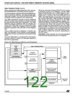
transfer from two DMA tables alternatively. All the
DMA descriptors in the Register File are thus dou-
bled. Two DMA transaction counters and two DMA
address pointers allow the definition of two fully in-
dependent tables (they only have to belong to the
same space, Register File or Memory). The DMA
transaction is programmed to start on one of the
two tables (say table 0) and, at the end of the
block, the DMA controller automatically swaps to
the other table (table 1) by pointing to the other
DMA descriptors. In this case, the DMA mask (DM
bit) control bit is not cleared, but the End Of Block
interrupt request is generated to allow the optional
updating of the first data table (table 0).
The interrupt and DMA arbitration protocol func-
tions completely asynchronously from instruction
flow.
Requests are sampled every 5 CPUCLK cycles.
DMA transactions are executed if their priority al-
lows it.
A DMA transfer with the Register file requires 8
CPUCLK cycles.
A DMA transfer with memory requires 16 CPUCLK
cycles, plus any required wait states.
6.5 SWAP MODE
Until the swap mode is disabled, the DMA control-
ler will continue to swap between DMA Table 0
and DMA Table 1.
An extra feature which may be found on the DMA
channels of some peripherals (e.g. the MultiFunc-
tion Timer) is the Swap mode. This feature allows
n
123/426
9

 STMICROELECTRONICS [ ST ]