ST92F124/F150/F250 - INTERRUPTS
5.7.2 IMPORTANT NOTE ON STANDARD
INTERRUPTS
Refer to Section 13.1.4 on page 412.
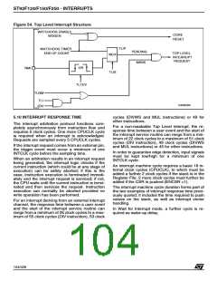
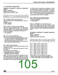
5.8 TOP LEVEL INTERRUPT
The Top Level Interrupt channel can be assigned
either to the external pin NMI or to the Timer/
Watchdog according to the status of the control bit
EIVR.TLIS (R246.2, Page 0). If this bit is high (the
reset condition) the source is the external pin NMI.
If it is low, the source is the Timer/ Watchdog End
Of Count. When the source is the NMI external
pin, the control bit EIVR.TLTEV (R246.3; Page 0)
selects between the rising (if set) or falling (if reset)
edge generating the interrupt request. When the
selected event occurs, the CICR.TLIP bit (R230.6)
is set. Depending on the mask situation, a Top
Level Interrupt request may be generated. Two
kinds of masks are available, a Maskable mask
and a Non-Maskable mask. The first mask is the
CICR.TLI bit (R230.5): it can be set or cleared to
enable or disable respectively the Top Level Inter-
rupt request. If it is enabled, the global Enable In-
terrupt bit, CICR.IEN (R230.4) must also be ena-
bled in order to allow a Top Level Request.
Warning. The interrupt machine cycle of the Top
Level Interrupt does not clear the CICR.IEN bit,
and the corresponding iretdoes not set it. Fur-
thermore the TLI never modifies the CPL bits and
the NICR register.
5.9 DEDICATED ON-CHIP PERIPHERAL
INTERRUPTS
Some of the on-chip peripherals have their own
specific interrupt unit containing one or more inter-
rupt channels, or DMA channels. Please refer to
the specific peripheral chapter for the description
of its interrupt features and control registers.
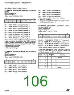
The on-chip peripheral interrupts are controlled by
the following bits:
– Interrupt Pending bit (IP). Set by hardware
when the Trigger Event occurs. Can be set/
cleared by software to generate/cancel pending
interrupts and give the status for Interrupt polling.
The second mask NICR.TLNM (R247.7) is a set-
only mask. Once set, it enables the Top Level In-
terrupt request independently of the value of
CICR.IEN and it cannot be cleared by the pro-
gram. Only the processor RESET cycle can clear
this bit. This does not prevent the user from ignor-
ing some sources due to a change in TLIS.
– Interrupt Mask bit (IM). If IM = “0”, no interrupt
request is generated. If IM =“1” an interrupt re-
quest is generated whenever IP = “1” and
CICR.IEN = “1”.
– Priority Level (PRL, 3 bits). These bits define
the current priority level, PRL=0: the highest pri-
ority, PRL=7: the lowest priority (the interrupt
cannot be acknowledged)
The Top Level Interrupt Service Routine cannot be
interrupted by any other interrupt or DMA request,
in any arbitration mode, not even by a subsequent
Top Level Interrupt request.
– Interrupt Vector Register (IVR, up to 7 bits).
The IVR points to the vector table which itself
contains the interrupt routine start address.
103/426
9

 STMICROELECTRONICS [ ST ]