Electrical characteristics
ST10F276E
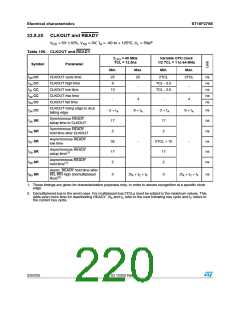
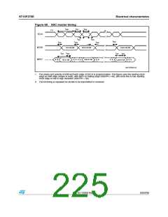
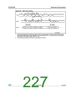
23.8.22 High-speed synchronous serial interface (SSC) timing modes
Master mode
VDD = 5V 10%, VSS = 0V, TA = -40 to +125°C, CL = 50pF
Table 108. Master mode
Max. baud rate 6.6Mbaud(1)
Variable baud rate
@ fCPU = 40 MHz
(<SSCBR> = 0002h)
(<SSCBR> = 0001h - FFFFh)
Symbol
Parameter
Unit
Min.
Max.
Min.
Max.
t300 CC SSC clock cycle time(2)
t301 CC SSC clock high time
t302 CC SSC clock low time
t303 CC SSC clock rise time
t304 CC SSC clock fall time
t305 CC Write data valid after shift edge
Write data hold after shift edge
150
150
8TCL
262144 TCL
63
-
t
300 / 2 - 12
-
10
15
10
15
-
-
t306 CC
- 2
- 2
3
Read data setup time before
t307p SR latch edge, phase error
ns
37.5
2TCL + 12.5
4TCL
detection on (SSCPEN = 1)
Read data hold time after latch
t308p SR edge, phase error detection on
(SSCPEN = 1)
50
25
0
-
-
Read data setup time before
t307 SR latch edge, phase error
detection off (SSCPEN = 0)
2TCL
Read data hold time after latch
t308 SR edge, phase error detection off
(SSCPEN = 0)
0
1. Maximum baud rate is in reality 8Mbaud, that can be reached with 64 MHz CPU clock and <SSCBR> set to
‘3h’, or with 48 MHz CPU clock and <SSCBR> set to ‘2h’. When 40 MHz CPU clock is used the maximum
baud rate cannot be higher than 6.6Mbaud (<SSCBR> = ‘2h’) due to the limited granularity of <SSCBR>.
Value ‘1h’ for <SSCBR> may be used only with CPU clock equal to (or lower than) 32 MHz (after checking
that timings are in line with the target slave).
2. Formula for SSC Clock Cycle time:
t300 = 4 TCL x (<SSCBR> + 1)
Where <SSCBR> represents the content of the SSC baud rate register, taken as unsigned 16-bit integer.
Minimum limit allowed for t300 is 125ns (corresponding to 8Mbaud)
224/235
Doc ID 12303 Rev 3

 STMICROELECTRONICS [ ST ]