ST10F276E
Electrical characteristics
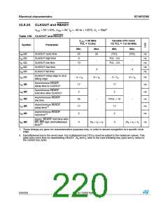
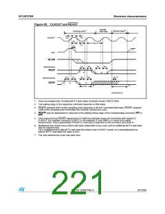
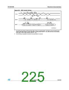
Figure 65. CLKOUT and READY
2%!$9
WAIT STATE
ꢀꢏ
ꢄꢏ
2UNNING CYCLE
-58ꢂTRIꢅSTATE
T
T
T
#,+/54
ꢈꢁ
ꢈꢈ
ꢈꢀ
T
T
ꢈꢉ
T
ꢁꢋ
ꢈꢇ
ꢊꢏ
!,%
2$ꢗ 72
ꢁꢏ
T
T
T
T
ꢈꢄ
ꢈꢃ
ꢈꢄ
ꢈꢃ
3YNCHRONOUS
2%!$9
ꢈꢏ
ꢈꢏ
ꢇꢏ
T
T
T
T
T
ꢄꢉ
ꢃꢆ
ꢃꢋ
ꢃꢆ
ꢃꢋ
!SYNCHRONOUS
2%!$9
ꢈꢏ
ꢈꢏ
ꢃꢏ
ꢄꢏ
T
ꢈꢊ
'!0'2)ꢉꢉꢀꢇꢁ
1. Cycle as programmed, including MCTC wait states (Example shows 0 MCTC WS).
2. The leading edge of the respective command depends on RW-delay.
3. READY sampled HIGH at this sampling point generates a READY controlled wait state, READY sampled
LOW at this sampling point terminates the currently running bus cycle.
4. READY may be deactivated in response to the trailing (rising) edge of the corresponding command (RD or
WR).
5. If the Asynchronous READY signal does not fulfill the indicated setup and hold times with respect to
CLKOUT (for example, because CLKOUT is not enabled), it must fulfill t in order to be safely
37
synchronized. This is guaranteed if READY is removed in response to the command (see Note 4).
6. Multiplexed bus modes have a MUX wait state added after a bus cycle, and an additional MTTC wait state
may be inserted here.
For a multiplexed bus with MTTC wait state this delay is two CLKOUT cycles; for a demultiplexed bus
without MTTC wait state this delay is zero.
7. The next external bus cycle may start here.
Doc ID 12303 Rev 3
221/235

 STMICROELECTRONICS [ ST ]