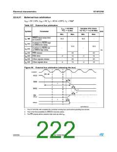
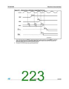
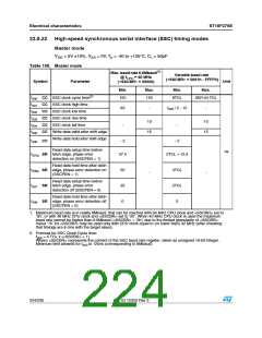
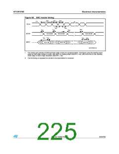
Electrical characteristics
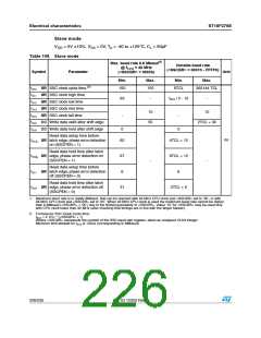
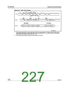
Slave mode
ST10F276E
VDD = 5V 10%, VSS = 0V, TA = -40 to +125°C, CL = 50pF
Table 109. Slave mode
Max. baud rate 6.6 Mbaud(1)
@ fCPU = 40 MHz
Variable baud rate
(<SSCBR> = 0001h - FFFFh)
Symbol
Parameter
Unit
(<SSCBR> = 0002h)
Min.
Max.
Min.
Max.
t310 SR SSC clock cycle time (2)
t311 SR SSC clock high time
150
150
8TCL
262144 TCL
63
-
t
310 / 2 - 12
-
t312 SR SSC clock low time
t313 SR SSC clock rise time
10
55
10
t314 SR SSC clock fall time
-
-
t315 CC Write data valid after shift edge
t316 CC Write data hold after shift edge
2TCL + 30
0
0
Read data setup time before
t317p SR latch edge, phase error detection
on (SSCPEN = 1)
ns
62
4TCL + 12
6TCL + 12
6
Read data hold time after latch
t318p SR edge, phase error detection on
(SSCPEN = 1)
87
6
-
-
Read data setup time before
t317 SR latch edge, phase error detection
off (SSCPEN = 0)
Read data hold time after latch
t318 SR edge, phase error detection off
(SSCPEN = 0)
31
2TCL + 6
1. Maximum baud rate is in reality 8Mbaud, that can be reached with 64 MHz CPU clock and <SSCBR> set to ‘3h’, or with
48 MHz CPU clock and <SSCBR> set to ‘2h’. When 40 MHz CPU clock is used the maximum baud rate cannot be higher
than 6.6Mbaud (<SSCBR> = ‘2h’) due to the limited granularity of <SSCBR>. Value ‘1h’ for <SSCBR> may be used only
with CPU clock lower than 32 MHz (after checking that timings are in line with the target master).
2. Formula for SSC Clock Cycle time:
t
= 4 TCL * (<SSCBR> + 1)
310
Where <SSCBR> represents the content of the SSC baud rate register, taken as unsigned 16-bit integer.
Minimum limit allowed for t is 125ns (corresponding to 8Mbaud).
310
226/235
Doc ID 12303 Rev 3

 STMICROELECTRONICS [ ST ]