Electrical characteristics
ST10F276E
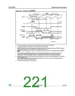
23.8.20 CLKOUT and READY
V
DD = 5V 10%, VSS = 0V, T = -40 to + 125°C, C = 50pF
A L
Table 106. CLKOUT and READY
fCPU = 40 MHz
TCL = 12.5ns
Variable CPU clock
1/2 TCL = 1 to 64 MHz
Symbol
Parameter
Min.
Max.
Min.
Max.
t29 CC
t30 CC
t31 CC
t32 CC
t33 CC
CLKOUT cycle time
CLKOUT high time
CLKOUT low time
CLKOUT rise time
CLKOUT fall time
25
9
25
2TCL
2TCL
ns
ns
ns
ns
ns
TCL - 3.5
TCL - 2.5
-
-
10
-
4
-
4
CLKOUT rising edge to ALE
falling edge
t34 CC
t35 SR
t36 SR
t37 SR
t58 SR
t59 SR
- 2 + tA
8 + tA
- 2 + tA
8 + tA
ns
ns
ns
ns
ns
ns
Synchronous READY
setup time to CLKOUT
17
2
17
Synchronous READY
hold time after CLKOUT
2
Asynchronous READY
low time
35
17
2
-
2TCL + 10
-
Asynchronous READY
setup time(1)
17
2
Asynchronous READY
hold time(1)
Async. READY hold time after
RD, WR high (Demultiplexed
Bus)(2)
t60 SR
0
2tA + tC + tF
0
2tA + tC + tF
ns
1. These timings are given for characterization purposes only, in order to assure recognition at a specific clock
edge.
2. Demultiplexed bus is the worst case. For multiplexed bus 2TCLs must be added to the maximum values. This
adds even more time for deactivating READY. 2tA and tC refer to the next following bus cycle and tF refers to
the current bus cycle.
220/235
Doc ID 12303 Rev 3

 STMICROELECTRONICS [ ST ]