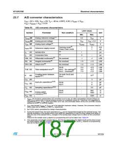
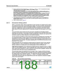
Electrical characteristics
ST10F276E
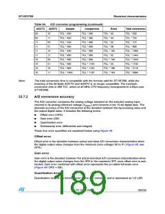
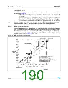
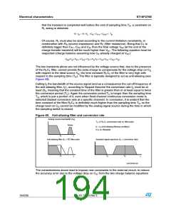
Nonlinearity error
Nonlinearity error is the deviation between actual and the best-fitting A/D conversion charac-
teristics (see Figure 46):
–
–
Differential nonlinearity error is the actual step dimension versus the ideal one (1
LSBIDEAL).
Integral nonlinearity error is the distance between the center of the actual step and
the center of the bisector line, in the actual characteristics. Note that for integral
nonlinearity error, the effect of offset, gain and quantization errors is not included.
Note:
Bisector characteristic is obtained drawing a line from 1/2 LSB before the first step of the
real characteristic, and 1/2 LSB after the last step again of the real characteristic.
23.7.3
Total unadjusted error
The total unadjusted error (TUE) specifies the maximum deviation from the ideal character-
istic: The number provided in the datasheet represents the maximum error with respect to
the entire characteristic. It is a combination of the offset, gain and integral linearity errors.
The different errors may compensate each other depending on the relative sign of the offset
and gain errors. Refer to Figure 46, see TUE.
Figure 46. A/D conversion characteristic
/FFSET ERROR /&3
'AIN ERROR '%
ꢈ&&
ꢈ&%
ꢍꢄꢏ
ꢈ&$
)DEAL CHARACTERISTIC
ꢈ&#
ꢈ&"
ꢈ&!
"ISECTOR CHARACTERISTIC
ꢍꢁꢏ
$IGITAL OUT
ꢍ(%8ꢏ
ꢉꢉꢊ
ꢍꢊꢏ
ꢍꢀꢏ
ꢉꢉꢄ
ꢉꢉꢃ
ꢍꢀꢏ %XAMPLE OF AN ACTUAL TRANSFER CURVE
ꢍꢁꢏ 4HE IDEAL TRANSFER CURVE
ꢍꢈꢏ $IFFERENTIAL NONLINEARITY ERROR ꢍ$.,ꢏ
ꢍꢇꢏ )NTEGRAL NONLINEARITY ERROR ꢍ).,ꢏ
ꢍꢃꢏ #ENTER OF A STEP OF THE ACTUAL TRANSFER CURVE
ꢍꢄꢏ 1UANTIZATION ERROR ꢍꢀꢂꢁ ,3"ꢏ
ꢍꢃꢏ
ꢉꢉꢇ
ꢉꢉꢈ
ꢍꢇꢏ
ꢉꢉꢁ
ꢉꢉꢀ
ꢉꢉꢉ
ꢍꢈꢏ
ꢍꢊꢏ 4OTAL UNADJUSTED ERROR ꢍ45%ꢏ
ꢀ ,3" ꢍIDEALꢏ
ꢀ
ꢁ
ꢈ
ꢇ
ꢃ
ꢄ
ꢊ
ꢀꢉꢀꢆ
ꢀꢉꢁꢉ
ꢀꢉꢁꢁ
ꢀꢉꢁꢇ
6
ꢍ,3"
ꢏ;,3"
ꢓ 6 ꢂꢀꢉꢁꢇ=
!2%&
!).
)$%!,
)$%!,
/FFSET ERROR /&3
'!0'2)ꢉꢉꢀꢁꢈ
190/235
Doc ID 12303 Rev 3

 STMICROELECTRONICS [ ST ]