ST10F276E
Electrical characteristics
23.7
A/D converter characteristics
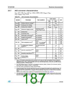
VDD = 5V 10%, VSS = 0V, TA = -40 to +125°C, 4.5V ≤ VAREF ≤ VDD
,
VSS ≤ VAGND ≤ VSS + 0.2V
Table 93. A/D converter characteristics
Limit values
Symbol
Parameter
Test condition
Unit
Min.
Max.
V
AREFSR
Analog reference voltage(1)
4.5
VSS
VDD
VSS + 0.2
VAREF
V
V
V
VAGNDSR Analog ground voltage
VAIN SR
AREFCC
Analog Input voltage(2)
VAGND
Running mode(3)
Power Down mode
-
-
5
1
mA
µA
I
Reference supply current
(4)
tS
tC
CC
CC
Sample time
1
3
-
µs
µs
(5)
Conversion time
-
DNL CC
INL CC
OFS CC
Differential nonlinearity(6)
Integral nonlinearity(6)
Offset error(6)
No overload
No overload
No overload
-1
+1
LSB
LSB
LSB
-1.5
-1.5
+1.5
+1.5
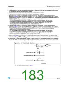
Port5
-2.0
-5.0
-7.0
+2.0
+5.0
+7.0
LSB
LSB
LSB
TUE CC
Total unadjusted error(6)
Port1 - No overload(3)
Port1 - Overload(3)
Coupling factor between
inputs(3)(7)
On both Port5 and
Port1
K
CC
-
-
-
-
10-6
3
-
CP1 CC
CP2 CC
CS CC
RSW CC
RAD CC
pF
Input pin capacitance(3)(8)
Sampling capacitance(3)(8)
Port5
Port1
4
6
pF
pF
3.5
pF
Port5
Port1
-
-
600
1600
Ω
Ω
Analog switch
resistance(3)(8)
-
1300
Ω
1.
V
can be tied to ground when A/D converter is not in use: An extra consumption (around 200µA) on
AREF
main V is added due to internal analog circuitry not completely turned off. Therefore, it is suggested to
DD
maintain the V
setting bit ADOFF in ADCON register.
at V level even when not in use, and eventually switch off the A/D converter circuitry
DD
AREF
2.
V
may exceed V or V up to the absolute maximum ratings. However, the conversion result in
AIN
AGND
AREF
these cases will be 0x000 or 0x3FF , respectively.
H
H
3. Not 100% tested, guaranteed by design characterization.
4. During the sample time, the input capacitance C can be charged/discharged by the external source. The
AIN
internal resistance of the analog source must allow the capacitance to reach its final voltage level within tS.
After the end of the sample time tS, changes of the analog input voltage have no effect on the conversion
result.
Values for the sample clock tS depend on programming and can be taken from Table 94.
5. This parameter includes the sample time tS, the time for determining the digital result and the time to load
the result register with the conversion result. Values for the conversion clock tCC depend on programming
and can be taken from next Table 94.
Doc ID 12303 Rev 3
187/235

 STMICROELECTRONICS [ ST ]