ST10F276E
Register set
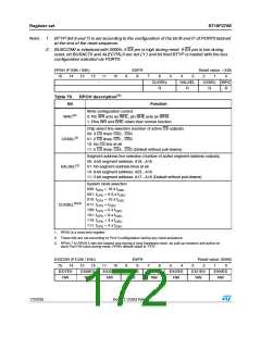
Table 80. EXIxES bit description
Bit
Function
00 = Fast external interrupts disabled: Standard mode.
EXxIN pin not taken in account for entering/exiting Power Down mode.
01 = Interrupt on positive edge (rising).
Enter Power Down mode if EXiIN = ‘0’, exit if EXxIN = ‘1’ (referred as "high" active
level)
EXIxES
(x=7...0)
10 = Interrupt on negative edge (falling).
Enter Power Down mode if EXiIN = ‘1’, exit if EXxIN = ‘0’ (referred as “low” active
level)
11 = Interrupt on any edge (rising or falling).
Always enter Power Down mode, exit if EXxIN level changed.
EXISEL (F1DAh / EDh)
15 14 13 12
ESFR
8
Reset value: 0000h
11
10
9
7
6
5
4
3
2
1
0
EXI7SS
RW
EXI6SS
RW
EXI5SS
RW
EXI4SS
RW
EXI3SS
RW
EXI2SS
RW
EXI1SS
RW
EXI0SS
RW
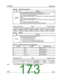
Table 81. EXISEL
Bit
Function
External Interrupt x Source Selection (x = 7...0)
00 = Input from associated Port 2 pin.
01 = Input from “alternate source”.
EXIxSS
10 = Input from Port 2 pin ORed with “alternate source”.
11 = Input from Port 2 pin ANDed with “alternate source”.
Table 82. EXIxSS and port 2 pin configurations
EXIxSS
Port 2 pin
Alternate source
CAN1_RxD
0
P2.8
1
P2.9
CAN2_RxD / SCL
RTCSI (Second)
RTCAI (Alarm)
Not used (zero)
2
P2.10
P2.11
P2.12...15
3
4...7
XP3IC (F19Eh / CFh)
ESFR
Reset value: --00h
15
-
14
-
13
-
12
-
11
-
10
-
9
-
8
-
7
6
5
4
3
2
1
0
XP3IR XP3IE
XP3ILVL
GLVL
RW RW
RW
RW
Note:
1. XP3IC register has the same bit field as xxIC interrupt registers
Doc ID 12303 Rev 3
173/235

 STMICROELECTRONICS [ ST ]