L7250
3.8.2 Gain Calibration Procedure
The Bemf detector circuitry must be calibrated right before the beginning of any Load/Unload operation.
Because the coil resistance can vary up to 30% due to thermal effects, it is necessary to calibrate the gain of
the first stage depending on the ratio between the operating coil resistance value and the sense resistance val-
ue.
The output of the Bemf detector circuiry is:
Bemf = OutP - OutM - Rs*Ivcm ( 1+ Rm/Rs)
where: Rm = motor resistance
Rs = sensing resistance
If the Gain of the first stage is matching the ratio between the coil resistance at operating temperature and the
sense resistor, the Bemf measured is right the value generated by the VCM motion.
The gain trimming is done with the VCM in a stop position (no Bemf must be generated) with a certain amount
of current flowing into the coil; in this condition the gain must be adjusted in order to have zero voltage from the
Bemf circuitry.
The gain adjusting is splitted in two phases. A coarse calibration is obtained setting the external resistor divider
at the CalCoarse pin (29) following the relation:
Vcontrol = [0.21 + (Rm/Rs) / 28.8]
Vcontrol max. range = Vbg ±0.75V
Where: Vbg = bandgap voltage (typ = 1.25)
A fine calibration is obtained by writing the internal register 02H -> b[3:0]. The fine calibration is used to com-
pensate the variation of the VCM coil resistance according with operating temperature condition.
The calibration is implemented moving the Vcontrol voltage by a percentage indicated on the RLcal table at
pag.17.
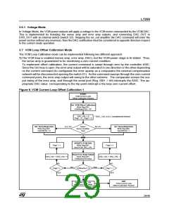
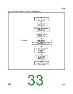
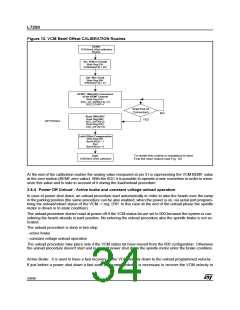
3.8.3 VCM Bemf offset trimming
Due to the high gain necessary to implement the BEMF reconstruction, the inpact of the offset on the output
value is very high. For this reason dedicated circuitry, using the 5 MSB of the AD converter, has been integrated
in order to compensate this offset.
The flow chart below reported are describing the method to implement the offset calibration.
32/46

 STMICROELECTRONICS [ ST ]