L7250
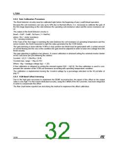
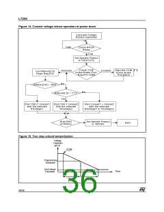
Figure 14. Costant voltage retract operation at power down
C onstant V oltage
R etract O peration
H igh
C heck N P O R
S tatus
Low
S et S pindle P ow ers
in T R IST A T E
C heck V C M
A ctive B rake P roc.
R eg.01H -bit[0]
S tart the V C M
A ctive B rake
P rocedure
(*)
D isabled
E nabled
G et R ltim er[2:0]
R ead R eg.01H
N o
R ltim er[2:0] = “000”
N o
R ltim er[2:0] = “111”
Y es
S tart O N LY U nload1
w ith the selected
R lvoltage1
S tart O N LY U nload2
w ith the selected
R lvoltage2
S tart U nload1 + U nload2
w ith the selected
R lvoltage1 & R lvoltage2
S et S pindle P ow ers
in B R A K E
W ait E N D
of R ltim er
E N D
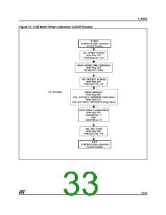
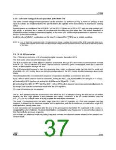
Figure 15. Two step unload temporization
Voltage
Capacitor
pin 21
POR
Programming
Threshold
End Unload
Threshold
Time
Step 1
Step 2
36/46

 STMICROELECTRONICS [ ST ]