L7250
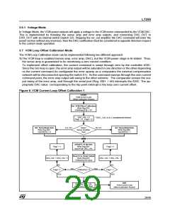
2) A second approach is considering to have the VCM in stop position; to enable it in current mode con-
figuration driving current in the right direction in order to be sure to mantain the stop position; to decre-
ment the 15bit DAC value to reach the zero current condition using the 10bit ADC to measure the
current value.
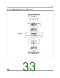
In the following diagram a detailed flow chart is presented.
Figure 10. VCM Current Loop Offset Calibration 2
START
Current Mode “ZeroIout”
Calibration Routine
No
Iout
Yes
EXIT with Error 1
Calibration not performed
Positive offset to big
Yes
Polarity check
ADC_DATA[9] = 0
Flag_A=0
No
Flag_A=0
DACvalue=1200 ( 0x4B0 )
Note 1
Flag_A=1
EXIT
StoreDACvalue
As reference for
ZEROIout
Set VCM inTristate
Write Reg.03H
VCMState[2:0] = 001
Current Mode “ZeroIout”
Calibration Routine
DACvalue-=1
Call
IoutDigitalVal Routine
Iout_Offset = ADC_DATA[9:0]
Note 2
Yes
EXIT with Error 2
Calibration not performed
Negative offset to big
START
IoutDigitalVal
Routine
DACvalue<-1200
No
Set 15BitDAC to have VCM Current
with no motion
Write Reg.09H & Reg.0Ah
Dac[14:0] = DACvalue
Set the GainSw to High or Low
START 10Bit ADC Conversion
of the Iout Channel
Write Reg.0CH
ADC_CH_ADDR[1:0] =00
ADC_START=1
ADC_DATA[9:0] -= Iout_offset
( Subtract the offset )
Set VCM in En.Current Mode
Write Reg.03H
VCMState [2:0] = 011
Wait End of
Conversion
NO
Read 10Bit ADC
Read Reg.0BH
ADC_DATA[9:2]
Read Reg.0CH
ADC_DATA[1:0]
YES
Wait 20msec
Update the 15BitDAC
Write Reg.09H & Reg.0Ah
Dac[14:0] =DACvalue
EXIT
IoutDigitalVal
Routine
Call
IoutDigitalVal
Routine
Note 1 : once the VCM will be enabled in current mode with the DAC value at 1200 the current will keep the motor against the crash stop position
Note 2 : with the VCM in tristate, the result of the digital conversion of the Iout Channel has to be used as ZERO current offset value
30/46

 STMICROELECTRONICS [ ST ]