L7250
order to avoid to rise the ramp or to meet the ID crash stop at high speed.
The over velocity detector circuit consist in a window comparator; in case of power failure the VCM power stage is tri-
µ
stated (for a fixed time about 200 s) in order to detect the amplitude of the Bemf generated by the VCM motion.
If the VCM Bemf is out of the window of the over velocity detector (this means that the heads are travelling at
high speed versus the inner or outer position), the active brake routine is invoked.
The voltage threshold ( = motor electrical constant * motor angular velocity), setting the over velocity detector
window, is set internally to 1.1V (to 0.4V if 5V application is considered).
At the contrary, if the VCM speed is inside the window (the heads where on track or moving slowly) the active
brake is skipped and the constant unload operation is commanded.
The active brake routine consist in a procedure that drive the VCM alternately with two steps:
- first activating the diagonal of the power stage in order to drive current in the right direction to slow down the
speed of the VCM for a time (RLTonBrake) that is half of the programmed RLToffBrake.
- then activating both the low side drivers of the power stage putting the VCM in short brake condition for a pro-
grammable time (RLToffBrake).
With the VCM in short brake the current into the coil is forced by the Bemf generated by the motion of the motor
and the sense amplifier output is sensed in order to detect indirectly the VCM speed.
The switch between the active brake routine and the constant voltage unload operation is done when the VCM current,
measured at the sense amplifier output during the short brake condition, fall down to zero (VCM is stopped).
The RLToffBrake (and so the RLTonBrake) time can be programmed by writing the Reg. 02H.
The active brake procedure can enabled/disabled by writing the Reg. 01H. In case the active brake procedure
is disabled, at power off the constant unload operation start immediately.
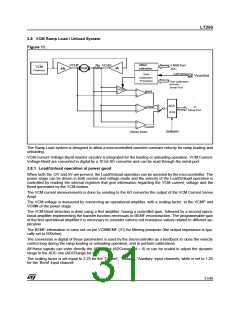
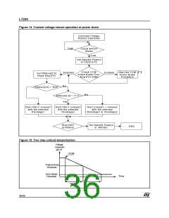
Constant Voltage Unload operation : a constant voltage (with a sink and source capability) is applied to the
VCM in order to drive the heads over the ramp in the parking position.
According with the contents of the registers REG. 01H it is possible to perform the unload operation in one or
two steps and for each steps to select the voltage level applied to the VCM.
The capacitor connected at the Timer1 (pin 28) define the total time of the unload operation ; during the unload
operation this capacitor is discharged by un internal constant current generator.
Programming the bit ‘b3b2b1’ of the REG. 01H it is possible to select different unload procedures:
With these bit set to 000 the unload is done in one step with the voltage selected by the two bit RLvoltage1 of
REG. 01H.
With these bit set to 111 the unload is done in one step with the voltage selected by the two bit RLvoltage2 of
REG. 01H.
The spindle motor is tristated during the unload operation
The other combinations of the bit ‘b3b2b1’ defines different threshold for the comparison with the discharging
voltage of the capacitor at pin 21 .
The timing for the first step is with the capacitor voltage greater then the programmed threshold, the timing for
the second step start when the capacitor voltage is below the threshold and end when the capacitor is dis-
charged under the 'end unload threshold' (0.2V typ) .
In all the cases, when the capacitor at pin 21 is discharged under the 'end unload threshold' the spindle motor
is driven inbrake condition.
The typical value of the retract procedure timing can be extimated using the following expression:
T = Tstep1 + Tstep2 = 1.15 * C
Where:
ext
Cext = External capacitor at pin ‘Timer1’ (28) measured in uF
35/46

 STMICROELECTRONICS [ ST ]