L7250
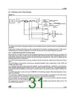
3.8 VCM Ramp Load / Unload System
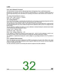
Figure 11.
Offset
calibration
5 MSB from
ADC
VCMP
VCMN
Rs
VCM
Predriver
VCM
+A
CalCoarse
Gain
Calibration
Procedure
29 Vcontrol
Fine calibration
bit from
_
Serial Port
_
VGA
Bemf
+
+
_
ADC
Voltage
to
Serial Port
+
10 bit
+
_
Current
Sel&start
(Sense Ampl)
The Ramp Load system is designed to allow a microcontrolled assisted constant velocity for ramp loading and
unloading.
VCM Current-Voltage-Bemf monitor circuitry is integrated for the loading or unloading operation. VCM Current-
Voltage-Bemf are converted in digital by a 10 bit AD converter and can be read through the serial port.
3.8.1 Load/Unload operation at power good
When both the 12V and 5V are present, the Load/Unload operation can be assisted by the microcontroller. The
power stage can be driven in both current and voltage mode and the velocity of the Load/Unload operation is
controlled by reading the internal registers that give information regarding the VCM current, voltage and the
Bemf generated by the VCM motion.
The VCM current measurements is done by sending to the AD converter the output of the VCM Current Sense
Ampl.
The VCM voltage is measured by connecting an operational amplifier, with a scaling factor, to the VCMP and
VCMN of the power stage.
The VCM Bemf detection is done using a first amplifier, having a controlled gain, followed by a second opera-
tional amplifier implementing the transfer function necessary to BEMF reconstruction. The programmable gain
of the first operational amplifier it is necessary to consider various coil resistance values related to different ap-
plication.
The BEMF information is carry out on pin VCMBEMF (31) for filtering pourpose (the output impedance is typi-
cally set to 500ohm).
The conversion in digital of these parameters is used by the microcontroller as a feedback to close the velocity
control loop during the ramp loading or unloading operation, and to perform calibrations.
All these signals can enter directly the ADC block (ADCrange bit = 0) or can be scaled to adjust the dynamic
range to the ADC one (ADCRange bit = 1).
The scaling factor is set equal to 2.25 for the ‘Current’, ‘Voltage’, ‘Auxiliary’ input channels, while is set to 1.25
for the ‘Bemf’ input channel.
31/46

 STMICROELECTRONICS [ ST ]