L7250
3
VOICE COIL MOTOR DRIVER
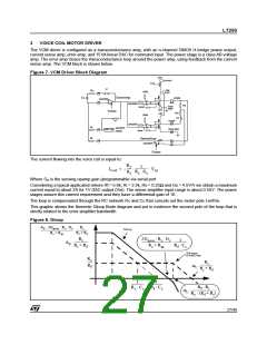
The VCM driver is configured as a transconductance amp, with an n-channel DMOS H-bridge power output,
current sense amp, error amp, and 15 bit linear DAC for command input. The power stage is a class AB voltage
amp. The error amp closes the transconductance loop around the power amp, using feedback from the current
sense amp. The VCM block is shown below.
Figure 7. VCM Driver Block Diagram
VCV
1/2/54/55
POR
S1
VM
Rc
VM/2
52/53
39
Cc
ErrorAmp
VCMN
DACREF
38
45/46
DACREF
Rs
VCM
GND
Gpow
43/44
VM
Tristate
Rm
Lm
VM/2
S2
VCMP
3/4
DACREF
Gpow
Ri
Rf
DACREF
AGND
VCM GND
5/6
37
40
DAC 15
SenseAmp
Gs
42
41
DACREF
Tristate
The current flowing into the voice coil is equal to:
= –
R
1
ƒ
----------------
s
------
I
V
in
coil
R
G
s
R
i
Where G is the sensing opamp gain (programmable via serial port
s
Ω
Considering a typical application where Rf = 5.6k, Ri = 2.5k, Rs = 0.25 and Gs = 4.5V/V we obtain a maximum
current equal to about 2A for 1V DAC output (Vin). The sense amplifier input range is about 0.55V. The power
stages assure this current requirement and they have a differential gain of 16.
The loop is compensated through the RC network Rc and Cc that cancels out the motor pole Lm/Rm.
This graphic shows the theoretic Gloop Bode diagram and put in evidence the second pole of the loop that is
strictly related to the error amplifier bandwidth.
Figure 8. Gloop
A 0 2Gpow Rs Gs
R i
G loop
------------------------------------------------- -----------------
Rs + Rm
R i + R f
R
2G
R
G
s s
1
i
pow
-----------------
-------------------------------------- ----------------
A
0
R + R
R + R
R
C
f c
i
f
s
m
Fdt error
closed loop
R
c
-----
R
i
R
-----------------
ω
f
t
R + R
i
f
1
1
---------------- ----------------
R
R
i
R
C
R
C
f c
f
c
c
--------------------------------
c
ω
t
R
(R + R )
f i
27/46

 STMICROELECTRONICS [ ST ]