A d v a n c e I n f o r m a t i o n
RY/BY#: Ready/Busy#
The device provides a RY/BY# open drain output pin as a way to indicate to the
host system that the Embedded Algorithms are either in progress or have been
completed. If the output is low, the device is busy with either a program, erase,
or reset operation. If the output is floating, the device is ready to accept any read/
write or erase operation. When the RY/BY# pin is low, the device will not accept
any additional program or erase commands with the exception of the Erase sus-
pend command. If the device has entered Erase Suspend mode, the RY/BY#
output will be floating. For programming, the RY/BY# is valid (RY/BY# = 0) after
the rising edge of the fourth WE# pulse in the four write pulse sequence. For chip
erase, the RY/BY# is valid after the rising edge of the sixth WE# pulse in the six
write pulse sequence. For sector erase, the RY/BY# is also valid after the rising
edge of the sixth WE# pulse.
If RESET# is asserted during a program or erase operation, the RY/BY# pin re-
mains a “0” (busy) until the internal reset operation is complete, which requires
a time of t
(during Embedded Algorithms). The system can thus monitor RY/
READY
BY# to determine whether the reset operation is complete. If RESET# is asserted
when a program or erase operation is not executing (RY/BY# pin is “floating”),
the reset operation is completed in a time of t
(not during Embedded Algo-
READY
rithms). The system can read data t after the RESET# pin returns to V .
RH
IH
Since the RY/BY# pin is an open-drain output, several RY/BY# pins can be tied
together in parallel with a pull-up resistor to V . An external pull-up resistor is
CC
required to take RY/BY# to a V level since the output is an open drain.
IH
Table 21 shows the outputs for RY/BY#. Figures 15, 19, 21 and 22 shows RY/BY#
for read, reset, program, and erase operations, respectively.
DQ6: Toggle Bit I
Toggle Bit I on DQ6 indicates whether an Embedded Program or Erase algorithm
is in progress or complete, or whether the device has entered the Erase Suspend
mode. Toggle Bit I may be read at any address, and is valid after the rising edge
of the final WE# pulse in the command sequence (prior to the program or erase
operation), and during the sector erase time-out.
During an Embedded Program or Erase algorithm operation, two immediately
consecutive read cycles to any address cause DQ6 to toggle. When the operation
is complete, DQ6 stops toggling. For asynchronous mode, either OE# or CE# can
be used to control the read cycles. For synchronous mode, the rising edge of
ADV# is used or the rising edge of clock while ADV# is Low.
After an erase command sequence is written, if all sectors selected for erasing
are protected, DQ6 toggles for approximately 100 µs, then returns to reading
array data. If not all selected sectors are protected, the Embedded Erase algo-
rithm erases the unprotected sectors, and ignores the selected sectors that are
protected.
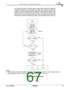
The system can use DQ6 and DQ2 together to determine whether a sector is ac-
tively erasing or is erase-suspended. When the device is actively erasing (that is,
the Embedded Erase algorithm is in progress), DQ6 toggles. When the device en-
ters the Erase Suspend mode, DQ6 stops toggling. However, the system must
also use DQ2 to determine which sectors are erasing or erase-suspended. Alter-
natively, the system can use DQ7 (see the subsection on DQ7: Data# Polling).
March 22, 2004 30606B0
S29CD032G
65

 SPANSION [ SPANSION ]