Highly Integrated Full Featured Hi-Speed USB 2.0 ULPI Transceiver
Datasheet
6.5.2
USB Audio Mode
When the USB3320 is powered in Synchronous Mode, the Audio switches can be enabled by asserting
the SpkLeftEn, or SpkRightEn bits in the Carkit Control register. After the register write is complete,
the USB3320 will immediately enable or disable the audio switch. Then the Link can set the
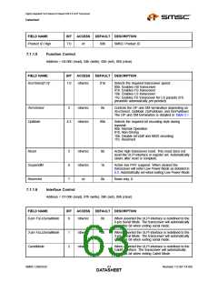
CarkitMode bit in the Interface Control register. The SpkLeftEn, or SpkRightEn bits must be written
before the CarkitMode bit.
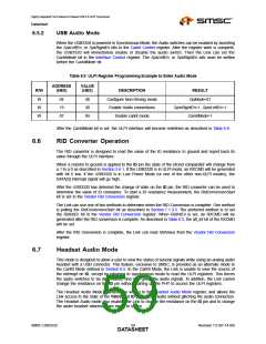
Table 6.9 ULPI Register Programming Example to Enter Audio Mode
ADDRESS
(HEX)
VALUE
(HEX)
R/W
DESCRIPTION
RESULT
W
W
W
04
19
07
48
30
04
Configure Non-Driving mode
Enable Audio connections
Enable carkit mode
OpMode=01
SpkrRightEn=1, SpkrLeftEn=1
CarkitMode=1
After the CarkitMode bit is set, the ULPI interface will become redefined as described in Table 6.8.
6.6
RID Converter Operation
The RID converter is designed to read the value of the ID resistance to ground and report back its
value through the ULPI interface.
When a resistor to ground is applied to the ID pin the state of the IdGnd comparator will change from
a 1 to a 0 as described in Section 5.6.1. If the USB3320 is in ULPI mode, an RXCMD will be generated
with bit 6 low. If the USB3320 is in Low Power Mode (or one of the other non-ULPI modes), the
DATA[3] interrupt signal will go high.
After the USB3320 has detected the change of state on the ID pin, the RID converter can be used to
determine the value of ID resistance. To start a ID resistance measurement, the RidConversionStart
bit is set in the Vendor Rid Conversion register.
The Link can use one of two methods to determine when the RID Conversion is complete. One method
is polling the RidConversionStart bit as described in Section 7.1.3.3. The preferred method is to set
the RidIntEn bit in the Vendor Rid Conversion register. When RidIntEn is set, an RXCMD will be
generated after the RID conversion is complete. As described in Table 6.3, the alt_int bit of the RXCMD
will be set.
After the RID Conversion is complete, the Link can read RidValue from the Vendor Rid Conversion
register.
6.7
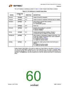
Headset Audio Mode
This mode is designed to allow a user to view the status of several signals while using an analog audio
headset with a USB connector. This feature, exclusive to SMSC, is provided as an alternate mode to
the CarKit Mode defined in Section 6.5. In the CarKit Mode, the Link is unable to view the source of
the interrupt on ID, except by returning to synchronous mode to read the ULPI registers. This forces
the audio switches to be deactivated, and may glitch the audio signals. In addition, the Link cannot
change the resistance on the ID pin without starting up the PHY to access the ULPI registers.
The Headset Audio Mode is entered by writing to the Headset Audio Mode register, and allows the
Link access to the state of the VBUS and ID pins during audio without glitching the audio connection.
The Headset Audio mode also enables the Link to change the resistance on the ID pin and to change
the audio headset attached from mono to stereo.
SMSC USB3320
Revision 1.0 (07-14-09)
DATA5S9HEET

 SMSC [ SMSC CORPORATION ]