Highly Integrated Full Featured Hi-Speed USB 2.0 ULPI Transceiver
Datasheet
6.5.1
USB UART Mode
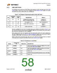
The USB3320 can be placed into UART Mode by first setting the TxdEn and RxdEn bits in the Carkit
Control register. Then the Link can set the CarkitMode bit in the Interface Control register. The TxdEn
and RxdEn bits must be written before the CarkitMode bit.
Table 6.7 ULPI Register Programming Example to Enter UART Mode
ADDRESS
(HEX)
VALUE
(HEX)
R/W
DESCRIPTION
RESULT
W
04
49
Configure Non-Driving mode
Select FS transmit edge rates
OpMode=01
XcvrSelect=01
W
W
39
19
00
Set regulator to 3.3V
UART RegOutput=00
0C
Enable UART connections
RxdEn=1
TxdEn=1
W
07
04
Enable carkit mode
CarkitMode=1
After the CarkitMode bit is set, the ULPI interface will become redefined as described in Table 6.8, and
the USB3320 will transmit data through the DATA[0] to DM of the USB connector and receive data on
DP and pass the information the Link on DATA[1].
When entering UART mode, the regulator output will automatically switch to the value configured by
the UART RegOutput bits in the USB IO & Power Management register and a pull-up will be applied
internally to DP and DM. This will hold the UART in its default operating state.
While in UART mode, the transmit edge rates can be set to either the Full Speed USB or Low Speed
USB edge rates by using the XcvrSelect[1:0] bits in the Function Control register.
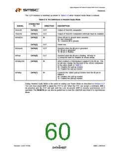
Table 6.8 Pin Definitions in Carkit Mode
CONNECTED
SIGNAL
TO
DIRECTION
DESCRIPTION
txd
rxd
DATA[0]
IN
UART TXD signal that is routed to the DM pin if the TxdEn
is set in the Carkit Control register.
DATA[1]
OUT
UART RXD signal that is routed to the DP pin if the RxdEn
bit is set in the Carkit Control register.
reserved
int
DATA[2]
DATA[3]
DATA[4:7]
OUT
OUT
OUT
Driven Low.
Asserted when any unmasked interrupt occurs. Active high.
Driven Low.
reserved
Revision 1.0 (07-14-09)
SMSC USB3320
DATA5S8HEET

 SMSC [ SMSC CORPORATION ]