Highly Integrated Full Featured Hi-Speed USB 2.0 ULPI Transceiver
Datasheet
6.3.3.1
Start up Protection
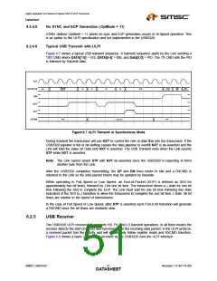
Upon start-up, when the transceiver de-asserts DIR, the Link must be ready to receive commands and
drive Idle on the data bus. If the Link is not ready to receive commands or drive Idle, it must assert
STP before DIR is de-asserted. The Link can then de-assert STP when it has completed its start-up.
If the Link doesn’t assert STP before it can receive commands, the transceiver may interpret the data
bus state as a TX CMD and transmit invalid data onto the USB bus, or make invalid register writes.
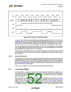
When the USB3320 sends a RXCMD the Link is required to drive the data bus back to idle at the end
of the turn around cycle. If the Link does not drive the databus to idle the USB3320 may take the
information on the data bus as a TXCMD and transmit data on DP and DM until the Link asserts stop.
If the ID pin is floated the last RXCMD from the USB3320 will remain on the bus after DIR is de-
asserted and the USB3320 will take this in as a TXCMD.
A Link should be designed to have the default POR state of the STP output high and the data bus tri-
stated. The USB3320 has weak pull-downs on the data bus to prevent these inputs from floating when
not driven. These resistors are only used to prevent the ULPI interface from floating during events
when the link ULPI pins may be tri-stated. The strength of the pull down resistors can be found in
Table 4.4. The pull downs are not strong enough to pull the data bus low after a ULPI RXCMD, the
Link must drive the data bus to idle after DIR is de-asserted.
In some cases, a Link may be software configured and not have control of its STP pin until after the
transceiver has started. In this case, the USB3320 has in internal pull-up on the STP input pad which
will pull STP high while the Link’s STP output is tri-stated. The STP pull-up resistor is enabled on POR
and can be disabled by setting the InterfaceProtectDisable bit 7 of the Interface Control register.
The STP pull-up resistor will pull-up the Link’s STP input high until the Link configures and drives STP
high. After the Link completes its start-up, STP can be synchronously driven low.
A Link design which drives STP high during POR can disable the pull-up resistor on STP by setting
InterfaceProtectDisable bit to 1. A motivation for this is to reduce the suspend current. In Low Power
Mode, STP is held low, which would draw current through the pull-up resistor on STP.
6.3.3.2
Warm Reset
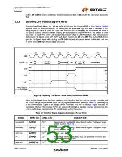
Designers should also consider the case of a warm restart of a Link with a transceiver in Low Power
Mode. After the transceiver enters Low Power Mode, DIR is asserted and the clock is stopped. The
USB3320 looks for STP to be asserted to re-start the clock and then resume normal synchronous
operation.
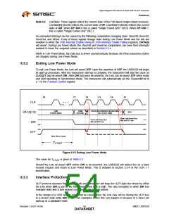
Should the USB3320 be suspended in Low Power Mode, and the Link receives a hardware reset, the
transceiver must be able to recover from Low Power Mode and start its clock. If the Link asserts STP
on reset, the transceiver will exit Low Power Mode and start its clock.
If the Link does not assert STP on reset, the interface protection pull-up can be used. When the Link
is reset, its STP output will tri-state and the pull-up resistor will pull STP high, signaling the transceiver
to restart its clock.
6.3.4
Minimizing Current in Low Power Mode
In order to minimize the suspend current in Low Power Mode, the OTG comparators can be disabled
to reduce suspend current. In Low Power Mode, the VbusVld and SessEnd comparators are not
needed and can be disabled by clearing the associated bits in both the USB Interrupt Enable Rising
and USB Interrupt Enable Falling registers. By disabling the interrupt in BOTH the rise and fall
registers, the SessEnd and VbusVld comparators are turned off. The IdFloatRise and IdFloatFall bits
in Carkit Interrupt Enable register should also be disabled if they were set. When exiting Low Power
Mode, the Link should immediately re-enable the VbusVld and SessEnd comparators if host or OTG
functionality is required.
In addition to disabling the OTG comparators in Low Power Mode, the Link may choose to disable the
Interface Protect Circuit. By setting the InterfaceProtectDisable bit high in the Interface Control register,
SMSC USB3320
Revision 1.0 (07-14-09)
DATA5S5HEET

 SMSC [ SMSC CORPORATION ]