Highly Integrated Full Featured Hi-Speed USB 2.0 ULPI Transceiver
Datasheet
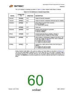
The ULPI interface is redefined as shown in Table 6.10 when Headset Audio Mode is entered.
Table 6.10 Pin Definitions in Headset Audio Mode
CONNECTED
SIGNAL
SessVld
TO
DIRECTION
OUT
DESCRIPTION
DATA[0]
DATA[1]
DATA[2]
Output of SessVld comparator
VbusVld
OUT
IN
Output of VbusVld Comparator (interrupt must be enabled)
IdGndDrv
Drives ID pin to ground when asserted
0b: Not connected
1b: Connects ID to ground.
DATA[3]
DATA[4]
OUT
OUT
Driven low
IdGround
Asserted when the ID pin is grounded.
0b: ID pin is grounded
1b: ID pin is floating
IdFloat
DATA[5]
DATA[6]
OUT
IN
Asserted when the ID pin is floating. IdPullup or
d_pullup330 must be enabled as shown below.
IdPullup330
When enabled a 330kΩpullup is applied to the ID pin. This
bit will also change the trip point of the IdGnd comparator
to the value shown in Table 4.7.
0b: Disables the pull-up resistor
1b: Enables the pull-up resistor
IdPullup
DATA[7]
IN
Connects the 100kΩ pull-up resistor from the ID pin to
VDD3.3
0b: Disables the pull-up resistor
1b: Enables the pull-up resistor
Exiting Headset Audio Mode is the same as exiting Low Power Mode as described in Section 6.3.2.
The Link must assert STP to signal the PHY to exit. When the PHY can accept a command, DIR is
de-asserted and the PHY will wait until the Link de-asserts STP to resume synchronous ULPI
operation. The RESETB pin can also be pulsed low to reset the USB3320 and return it to Synchronous
Mode.
Revision 1.0 (07-14-09)
SMSC USB3320
DATA6S0HEET

 SMSC [ SMSC CORPORATION ]