Highly Integrated Full Featured Hi-Speed USB 2.0 ULPI Transceiver
Datasheet
on the DP and DM pins to avoid false linestate indications that could result if the pins were allowed to
float.
6.3.1
Entering Low Power/Suspend Mode
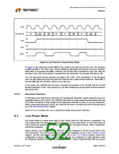
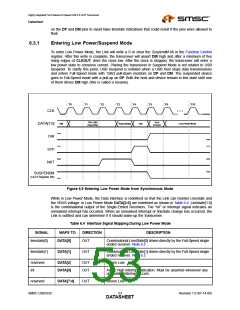
To enter Low Power Mode, the Link will write a 0 or clear the SuspendM bit in the Function Control
register. After this write is complete, the transceiver will assert DIR high and after a minimum of five
rising edges of CLKOUT, drive the clock low. After the clock is stopped, the transceiver will enter a
low power state to conserve current. Placing the transceiver in Suspend Mode is not related to USB
Suspend. To clarify this point, USB Suspend is initiated when a USB host stops data transmissions
and enters Full-Speed mode with 15KΩ pull-down resistors on DP and DM. The suspended device
goes to Full-Speed mode with a pull-up on DP. Both the host and device remain in this state until one
of them drives DM high (this is called a resume).
T0
T1
T2
T3
T4
T5
T6
T10
...
CLK
TXD CMD
(reg write)
Turn
Around
Idle
Reg Data[n]
Idle
Low Power Mode
DATA[7:0]
DIR
STP
NXT
SUSPENDM
(ULPI Register Bit)
Figure 6.9 Entering Low Power Mode from Synchronous Mode
While in Low Power Mode, the Data interface is redefined so that the Link can monitor Linestate and
the VBUS voltage. In Low Power Mode DATA[3:0] are redefined as shown in Table 6.4. Linestate[1:0]
is the combinational output of the Single-Ended Receivers. The “int” or interrupt signal indicates an
unmasked interrupt has occurred. When an unmasked interrupt or linestate change has occurred, the
Link is notified and can determine if it should wake-up the transceiver.
Table 6.4 Interface Signal Mapping During Low Power Mode
SIGNAL
MAPS TO
DATA[0]
DIRECTION
DESCRIPTION
linestate[0]
OUT
Combinatorial LineState[0] driven directly by the Full-Speed single
ended receiver. Note 6.2
linestate[1]
DATA[1]
OUT
Combinatorial LineState[1] driven directly by the Full-Speed single
ended receiver. Note 6.2
reserved
int
DATA[2]
OUT
OUT
Driven Low
DATA[3]
Active high interrupt indication. Must be asserted whenever any
unmasked interrupt occurs.
reserved
DATA[7:4]
OUT
Driven Low
SMSC USB3320
Revision 1.0 (07-14-09)
DATA5S3HEET

 SMSC [ SMSC CORPORATION ]