Highly Integrated Full Featured Hi-Speed USB 2.0 ULPI Transceiver
Datasheet
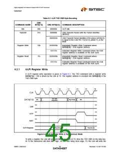
Table 6.3 ULPI RX CMD Encoding
DESCRIPTION AND VALUE
DATA[7:0]
NAME
[1:0]
[3:2]
Linestate
UTMI Linestate Signals Note 6.1
Encoded
VBUS
State
ENCODED VBUS VOLTAGE STATES
VALUE
VBUS VOLTAGE
SESSEND
SESSVLD
VBUSVLD2
00
01
VVBUS < VSESS_END
1
0
0
0
0
0
V
SESS_END < VVBUS
<
<
VSESS_VLD
10
11
VSESS_VLD < VVBUS
VVBUS_VLD
X
X
1
0
1
VVBUS_VLD < VVBUS
X
[5:4]
Rx Event
Encoding
ENCODED UTMI EVENT SIGNALS
VALUE
RXACTIVE
RXERROR
HOSTDISCONNECT
00
01
11
10
0
1
1
X
0
0
1
X
0
0
0
1
[6]
[7]
State of
ID pin
Set to the logic state of the ID pin. A logic low indicates an A device. A logic high
indicates a B device.
alt_int
Asserted when a non-USB interrupt occurs. This bit is set when an unmasked event
occurs on any bit in the Carkit Interrupt Latch register. The Link must read the Carkit
Interrupt Latch register to determine the source of the interrupt. Section 5.6.1.3
describes how a change on the ID pin can generate an interrupt. Section 6.6
describes how an interrupt can be generated when the RidConversionDone bit is set.
Notes:
1. An ‘X’ is a do not care and can be either a logic 0 or 1.
2. The value of VbusValid is defined in Table 5.6.
Note 6.1 LineState: These bits in the RXCMD byte reflect the current state of the Full-Speed single
ended receivers. LineState[0] directly reflects the current state of DP. LineState[1] directly
reflects the current state of DM. When DP=DM=0 this is called "Single Ended Zero" (SE0).
When DP=DM=1, this is called "Single Ended One" (SE1).
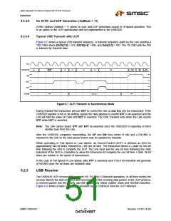
6.2.4
USB3320 Transmitter
The USB3320 ULPI transmitter fully supports HS, FS, and LS transmit operations. Figure 6.1 shows
the high speed, full speed, and low speed transmitter block controlled by ULPI Protocol Block.
Encoding of the USB packet follows the bit-stuffing and NRZI outlined in the USB 2.0 specification.
Many of these functions are re-used between the HS and FS/LS transmitters. When using the
USB3320, Table 5.1 should always be used as a guideline on how to configure for various modes of
operation. The transmitter decodes the inputs of XcvrSelect[1:0], TermSelect, OpMode[1:0],
DpPulldown, and DmPulldown to determine what operation is expected. Users must strictly adhere to
the modes of operation given in Table 5.1.
SMSC USB3320
Revision 1.0 (07-14-09)
DATA4S9HEET

 SMSC [ SMSC CORPORATION ]