Highly Integrated Full Featured Hi-Speed USB 2.0 ULPI Transceiver
Datasheet
5.6.2.4
VBUS Pulsing with Pull-up and Pull-down Resistors
In addition to the internal VBUS comparators, the USB3320 also includes the integrated VBUS pull-up
and pull-down resistors used for VBUS Pulsing during OTG Session Request Protocol. To discharge
the VBUS voltage so that a Session Request can begin, the USB3320 provides a pull-down resistor
from VBUS to Ground. This resistor is controlled by the DischargeVbus bit 3 of the OTG Control
register. The pull-up resistor is connected between VBUS and VDD33. This resistor is used to pull
VBUS above 2.1 volts so that the A-Device knows that a USB session has been requested. The state
of the pull-up resistor is controlled by the bit 4 ChargeVbus of the OTG Control register. The Pull-Up
and Pull-Down resistor values are detailed in Table 4.7.
The internal VBUS Pull-up and Pull-down resistors are designed to include the RVBUS external resistor
in series. This external resistor is used by the VBUS Overvoltage protection described below.
5.6.2.5
5.6.2.6
VBUS Input Impedance
The OTG Supplement requires an A-Device that supports Session Request Protocol to have a VBUS
input impedance less than 100kΩ and greater the 40kΩ to ground. The USB3320 provides a 75kΩ
resistance to ground, RVB. The RVB resistor tolerance is detailed in Table 4.7.
VBUS Overvoltage Protection
The USB3320 provides an integrated overvoltage protection circuit to protect the VBUS pin from
excessive voltages that may be present at the USB connector. The overvoltage protection circuit works
with an external resistor (RVBUS) by drawing current across the resistor to reduce the voltage at the
VBUS pin.
When voltage at the VBUS pin exceeds 5.5V, the Overvoltage Protection block will sink current to
ground until VBUS is below 5.5V. The current drops the excess voltage across RVBUS and protects the
USB3320 VBUS pin. The required RVBUS value is dependent on the operating mode of the USB3320
as shown in Table 5.7.
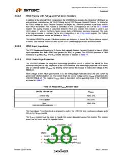
Table 5.7 Required RVBUS Resistor Value
OPERATING MODE
RVBUS
Device only
10kΩ ±5%
1kΩ ±5%
10kΩ ±5%
OTG Capable
Host
UseExternalVbusIndicator = 1
The Overvoltage Protection circuit is designed to protect the USB3320 from continuous voltages up to
30V on the RVBUS resistor.
The RVBUS resistor must be sized to handle the power dissipated across the resistor. The resistor
power can be found using the equation below:
2
(Vprotect – 5.0)
P
= -------------------------------------------
RVBUS
R
VBUS
Where:
Vprotect is the VBUS protection required
RVBUS is the resistor value, 1kΩ or 10kΩ.
PRVBUS is the required power rating of RVBUS
Revision 1.0 (07-14-09)
SMSC USB3320
DATA3S8HEET

 SMSC [ SMSC CORPORATION ]