Highly Integrated Full Featured Hi-Speed USB 2.0 ULPI Transceiver
Datasheet
For example, protecting a peripheral or device only application to 15V would require a 10kΩ RVBUS
resistor with a power rating of 0.01W. To protect an OTG product to 15V would require a 1kΩ RVBUS
resistor with a power rating of 0.1W.
5.6.3
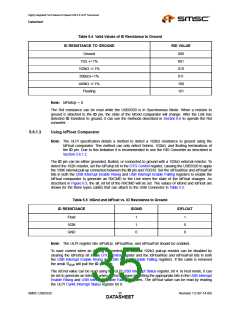
Driving External VBUS
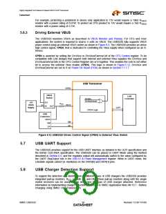
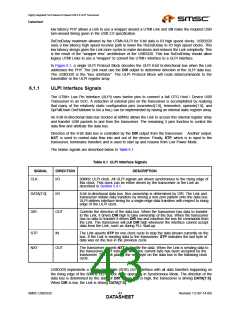
The USB3320 monitors VBUS as described in VBUS Monitor and Pulsing. For OTG and Host
applications, the system is required to source 5 volts on VBUS. The USB3320 fully supports VBUS
power control using an external VBUS switch as shown in Figure 8.3. The USB3320 provides an active
high control signal, CPEN, that is dedicated to controlling the Vbus supply when configured as an A-
Device.
CPEN is asserted by setting the DrvVbus or DrvVbusExternal bit of the OTG Control register. To be
compatible with Link designs that support both internal and external Vbus supplies the DrvVbus and
DrvVbusExternal bits in the OTG Control Register are or’d together. This enables the Link to set either
bit to access the external Vbus enable (CPEN). This logic is shown in Figure 5.12. DrvVbus and
DrvVbusExternal are set to 0 on Power On Reset (POR) as shown in Section 7.1.1.7.
USB Transceiver
CPEN
VBUS
Switch
Link
Controller
DrvVbus
DrvVbusExternal
EN
+5V
VBUS
Supply
RVBUS
VBUS
5V
IN OUT
ULPI
CPEN Logic
USB
Connector
VBUS
DM
DP
DM
DP
Figure 5.12 USB3320 Drives Control Signal (CPEN) to External Vbus Switch
5.7
5.8
USB UART Support
The USB3320 provides support for the USB UART interface as detailed in the ULPI specification and
the former CEA-936A specification. The USB3320 can be placed in UART Mode using the method
described in Section 6.5, and the regulator output will automatically switch to the value configured by
the UART RegOutput bits in the USB IO & Power Management register. While in UART mode, the
Linestate signals cannot be monitored on the DATA[0] and DATA[1] pins.
USB Charger Detection Support
To support the detection and identification of different types of USB chargers the USB3320 provides
integrated pull-up resistors, RCD, on both DP and DM. These pull-up resistors along with the single
ended receivers can be used to help determine the type of USB charger attached. Reference
information on implementing charger detection is provided in SMSC Application Note AN 19.7 - Battery
Charging Using SMSC USB Transceivers.
SMSC USB3320
Revision 1.0 (07-14-09)
DATA3S9HEET

 SMSC [ SMSC CORPORATION ]