Highly Integrated Full Featured Hi-Speed USB 2.0 ULPI Transceiver
Datasheet
Table 5.4 Valid Values of ID Resistance to Ground
ID RESISTANCE TO GROUND
RID VALUE
Ground
75Ω +/-1%
102kΩ +/-1%
200kΩ+/-1%
440kΩ +/-1%
Floating
000
001
010
011
100
101
Note: IdPullUp = 0
The Rid resistance can be read while the USB3320 is in Synchronous Mode. When a resistor to
ground is attached to the ID pin, the state of the IdGnd comparator will change. After the Link has
detected ID transition to ground, it can use the methods described in Section 6.6 to operate the Rid
converter.
5.6.1.3
Using IdFloat Comparator
Note: The ULPI specification details a method to detect a 102kΩ resistance to ground using the
IdFloat comparator. This method can only detect 0ohms, 102kΩ, and floating terminations of
the ID pin. Due to this limitation it is recommended to use the RID Converter as described in
Section 5.6.1.2.
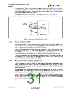
The ID pin can be either grounded, floated, or connected to ground with a 102kΩ external resistor. To
detect the 102K resistor, set the idPullup bit in the OTG Control register, causing the USB3320 to apply
the 100K internal pull-up connected between the ID pin and VDD33. Set the idFloatRise and idFloatFall
bits in both the USB Interrupt Enable Rising and USB Interrupt Enable Falling registers to enable the
IdFloat comparator to generate an RXCMD to the Link when the state of the IdFloat changes. As
described in Figure 6.3, the alt_int bit of the RXCMD will be set. The values of IdGnd and IdFloat are
shown for the three types cables that can attach to the USB Connector in Table 5.5.
Table 5.5 IdGnd and IdFloat vs. ID Resistance to Ground
ID RESISTANCE
IDGND
IDFLOAT
Float
102K
GND
1
1
0
1
0
0
Note: The ULPI register bits IdPullUp, IdFloatRise, and IdFloatFall should be enabled.
To save current when an A Plug is inserted, the internal 102kΩ pull-up resistor can be disabled by
clearing the IdPullUp bit in the OTG Control register and the IdFloatRise and IdFloatFall bits in both
the USB Interrupt Enable Rising and USB Interrupt Enable Falling registers. If the cable is removed
the weak RIDW will pull the ID pin high.
The IdGnd value can be read using the ULPI USB Interrupt Status register, bit 4. In host mode, it can
be set to generate an interrupt when IdGnd changes by setting the appropriate bits in the USB Interrupt
Enable Rising and USB Interrupt Enable Falling registers. The IdFloat value can be read by reading
the ULPI Carkit Interrupt Status register bit 0.
SMSC USB3320
Revision 1.0 (07-14-09)
DATA3S5HEET

 SMSC [ SMSC CORPORATION ]