Highly Integrated Full Featured Hi-Speed USB 2.0 ULPI Transceiver
Datasheet
~
~
VDD33
IdPullup
ID
To USB Con.
IdGnd
Vref IdGnd
IdGnd Rise or
en
IdGnd Fall
IdGndDrv
IdFloat
Vref IdFloat
IdFloatRise or
en
IdFloatFall
RidValue
Rid ADC
OTG Module
~
~
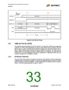
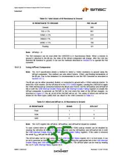
Figure 5.10 USB3320 ID Resistor Detection Circuitry
5.6.1.1
USB OTG Operation
The USB3320 can detect ID grounded and ID floating to determine if an A or B cable has been
inserted. The A plug will ground the ID pin while the B plug will float the ID pin. These are the only
two valid states allowed in the OTG Protocol.
To monitor the status of the ID pin, the Link activates the IdPullup bit in the OTG Control register, waits
50mS and then reads the status of the IdGnd bit in the USB Interrupt Status register. If an A cable has
been inserted the IdGnd bit will read 0. If a B cable is inserted, the ID pin is floating and the IdGnd bit
will read 1.
The USB3320 provides an integrated weak pull-up resistor on the ID pin, RIDW. This resistor is present
to keep the ID pin in a known state when the IdPullup bit is disabled and the ID pin is floated. In
addition to keeping the ID pin in a known state, it enables the USB3320 to generate an interrupt to
inform the link when a cable with a resistor to ground has been attached to the ID pin. The weak pull-
up is small enough that the largest valid Rid resistor pulls the ID pin low and causes the IdGnd
comparator to go low.
After the link has detected an ID pin state change, the RID converter can be used to determine the
resistor value as described in Section 5.6.1.2.
5.6.1.2
Measuring ID Resistance to Ground
The Link can used the integrated resistance measurement capabilities to determine the value of an ID
resistance to ground. Table 5.4 lists the valid values of resistance, to ground, that the USB3320 can
detect.
Revision 1.0 (07-14-09)
SMSC USB3320
DATA3S4HEET

 SMSC [ SMSC CORPORATION ]