Highly Integrated Full Featured Hi-Speed USB 2.0 ULPI Transceiver
Datasheet
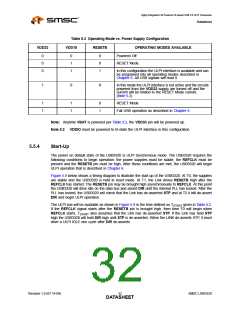
Table 5.3 Operating Mode vs. Power Supply Configuration
VDD33
VDD18
RESETB
OPERATING MODES AVAILABLE
Powered Off
0
0
0
0
1
1
0
0
1
RESET Mode.
In this configuration the ULPI interface is available and can
be programed into all operating modes described in
Chapter 6. All USB signals will read 0.
1
0
X
In this mode the ULPI interface is not active and the circuits
powered from the VDD33 supply are turned off and the
current will be limited to the RESET Mode current.
(Note 5.2)
1
1
1
1
0
1
RESET Mode
Full USB operation as described in Chapter 6.
Note: Anytime VBAT is powered per Table 3.2, the VDD33 pin will be powered up.
Note 5.2 VDDIO must be powered to tri-state the ULPI interface in this configuration.
5.5.4
Start-Up
The power on default state of the USB3320 is ULPI Synchronous mode. The USB3320 requires the
following conditions to begin operation: the power supplies must be stable, the REFCLK must be
present and the RESETB pin must be high. After these conditions are met, the USB3320 will begin
ULPI operation that is described in Chapter 6.
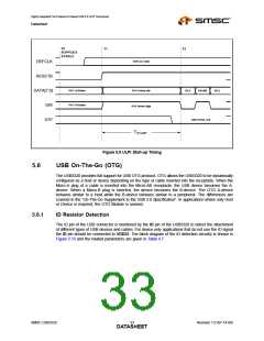
Figure 5.9 below shows a timing diagram to illustrate the start-up of the USB3320. At T0, the supplies
are stable and the USB3320 is held in reset mode. At T1, the Link drives RESETB high after the
REFCLK has started. The RESETB pin may be brought high asynchronously to REFCLK. At this point
the USB3320 will drive idle on the data bus and assert DIR until the internal PLL has locked. After the
PLL has locked, the USB3320 will check that the Link has de-asserted STP and at T2 it will de-assert
DIR and begin ULPI operation.
The ULPI bus will be available as shown in Figure 5.9 in the time defined as TSTART given in Table 4.2.
If the REFCLK signal starts after the RESETB pin is brought high, then time T0 will begin when
REFCLK starts. TSTART also assumes that the Link has de-asserted STP. If the Link has held STP
high the USB3320 will hold DIR high until STP is de-asserted. When the LINK de-asserts STP, it must
drive a ULPI IDLE one cycle after DIR de-asserts.
Revision 1.0 (07-14-09)
SMSC USB3320
DATA3S2HEET

 SMSC [ SMSC CORPORATION ]