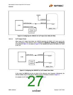
Highly Integrated Full Featured Hi-Speed USB 2.0 ULPI Transceiver
Datasheet
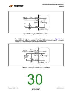
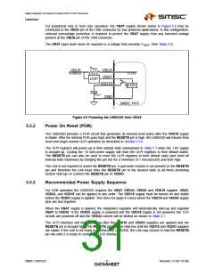
For peripheral only or host only operation, the VBAT supply shown below in Figure 5.8 may be
connected to the VBUS pin of the USB connector for bus powered applications. In this configuration,
external overvoltage protection is required to protect the VBAT supply from any transient voltage
present at the VBUS pin of the USB connector.
The VBAT input must never be exposed to a voltage that exceeds VVBAT. (See Table 3.2)
~
~
RVBUS
VBUS
VBUS
VBAT
To USB Con.
To OTG
OVP
VDD33
LDO
COUT
GND
SMSC PHY
~
~
Figure 5.8 Powering the USB3320 from VBUS
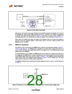
5.5.2
Power On Reset (POR)
The USB3320 provides a POR circuit that generates an internal reset pulse after the VDD18 supply
is stable. After the internal POR goes high and the RESETB pin is high, the USB3320 will release from
reset and begin normal ULPI operation as described in Section 5.5.4.
The ULPI registers will power up in their default state summarized in Table 7.1 when the 1.8V supply
is brought up. Cycling the 1.8 volt power supply will reset the ULPI registers to their default states.
The RESETB pin can also be used to reset the ULPI registers to their default state (and reset all
internal state machines) by bringing the pin low for a minimum of 1 microsecond and then high.
The Link is not required to assert the RESETB pin. A pull-down resistor is not present on the RESETB
pin and therefore the Link must drive the RESETB pin to the desired state at all times (including
system start-up) or connect the RESETB pin to VDDIO.
5.5.3
Recommended Power Supply Sequence
For USB operation the USB3320 requires the VBAT, VDD33, VDDIO and VDD18 supples. VBAT,
VDD33, and VDD18 can be applied in any order. The VDD18 supply must be turned on and stable
before the VDDIO supply is applied. This does not apply in cases where the VDD18 and VDDIO supply
pins are tied together.
When the VBAT supply is applied, the integrated regulator will automatically start-up and regulate
VBAT to VDD33. If the VDD33 supply is powered and the VDD18 supply is not powered, the 3.3V
circuits are powered off and the VDD33 current will be limited as shown in Table 4.1.
The ULPI interface will start operating after the VDD18 and VDDIO supplies are applied and the
RESETB pin is brought high. The RESETB pin must be held low until the VDD18 and VDDIO supplies
are stable. If the Link is not ready to interface the USB3320, the Link may choose to hold the RESETB
pin low until it is ready to control the ULPI interface.
SMSC USB3320
Revision 1.0 (07-14-09)
DATA3S1HEET

 SMSC [ SMSC CORPORATION ]