Highly Integrated Full Featured Hi-Speed USB 2.0 ULPI Transceiver
Datasheet
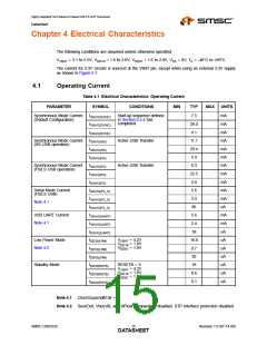
Chapter 4 Electrical Characteristics
The following conditions are assumed unless otherwise specified:
VVBAT = 3.1 to 5.5V; VDD18 = 1.6 to 2.0V; VDDIO = 1.6 to 2.0V; VSS = 0V; TA = -40°C to +85°C
The current for 3.3V circuits is sourced at the VBAT pin, except when using an external 3.3V supply
as shown in Figure 5.7.
4.1
Operating Current
Table 4.1 Electrical Characteristics: Operating Current
PARAMETER
SYMBOL
CONDITIONS
MIN
TYP
MAX
UNITS
Synchronous Mode Current
(Default Configuration)
I33AVG(SYNC)
I18AVG(SYNC)
IIOAVG(SYNC)
I33AVG(HS)
Start-up sequence defined
in Section 5.5.4 has
completed.
7.5
28.0
4.1
11.1
29.4
5.9
6.3
22.5
5.0
5.6
2.4
86
mA
mA
mA
mA
mA
mA
mA
mA
mA
mA
mA
uA
Synchronous Mode Current
(HS USB operation)
Active USB Transfer
Active USB Transfer
I18AVG(HS)
IIOAVG(HS)
Synchronous Mode Current
(FS/LS USB operation)
I33AVG(FS)
I18AVG(FS)
IIOAVG(FS)
Serial Mode Current
(FS/LS USB)
I33AVG(FS_S)
I18AVG(FS_S)
IIOAVG(FS_S)
I33AVG(UART)
I18AVG(UART)
IIOAVG(UART)
IDD33(LPM)
IDD18(LPM)
IDDIO(LPM)
Note 4.1
USB UART Current
Note 4.1
5.6
2.4
58
mA
mA
uA
Low Power Mode
Note 4.2
VVBAT = 4.2V
VDD18 = 1.8V
VDDIO = 1.8V
18.8
0.7
30
uA
uA
uA
Standby Mode
IDD33(RSTB)
IDD18(RSTB)
IDDIO(RSTB)
RESETB = 0
VVBAT = 4.2V
VDD18 = 1.8V
VDDIO = 1.8V
18
uA
0.6
0.1
uA
uA
Note 4.1 ClockSuspendM bit = 0.
Note 4.2 SessEnd, VbusVld, and IdFloat comparators disabled. STP Interface protection disabled.
SMSC USB3320
Revision 1.0 (07-14-09)
DATA1S5HEET

 SMSC [ SMSC CORPORATION ]