Highly Integrated Full Featured Hi-Speed USB 2.0 ULPI Transceiver
Datasheet
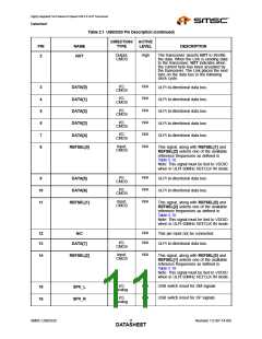
Table 2.1 USB3320 Pin Description (continued)
DIRECTION/ ACTIVE
PIN
17
NAME
CPEN
TYPE
LEVEL
DESCRIPTION
Output,
CMOS
N/A
External 5V supply enable. Controls the
external VBUS power switch. CPEN is low
on POR.
I/O,
N/A
N/A
N/A
D+ pin of the USB cable.
18
19
20
DP
DM
Analog
I/O,
Analog
D- pin of the USB cable.
Power
3.3V Regulator Output. A 2.2uF (<1 ohm
ESR) bypass capacitor to ground is
required for regulator stability. The
bypass capacitor should be placed as
close as possible to the USB3320.
VDD33
Power
N/A
N/A
Regulator input.
21
22
VBAT
VBUS
I/O,
Analog
This pin connects to an external resistor
(RVBUS) connected to the VBUS pin of
the USB cable. This pin is used for the
VBUS comparator inputs and for VBUS
pulsing during session request protocol.
See Table 5.7, "Required RVBUS
Resistor Value".
Input,
N/A
N/A
ID pin of the USB cable. For applications
not using ID this pin can be connected to
VDD33. For an A-Device ID is grounded.
For a B-Device ID is floated.
23
24
ID
Analog
Analog,
CMOS
Bias Resistor pin. This pin requires an
8.06kΩ (±1%) resistor to ground, placed
as close as possible to the USB3320.
Nominal voltage during ULPI operation is
0.8V.
RBIAS
Output,
CMOS
N/A
N/A
External resonator pin. When using an
external clock on REFCLK, this pin
should be floated.
25
26
XO
Input,
CMOS
ULPI Output Clock Mode:
Reference frequency as defined in
Table 5.10.
ULPI Input Clock Mode:
60MHz ULPI clock input.
REFCLK
Input,
CMOS,
Low
When low, the part is suspended with all
ULPI outputs tri-stated. When high, the
USB3320 will operate as a normal ULPI
device, as described in Section 5.5.2.
The state of this pin may be changed
asynchronously to the clock signals.
When asserted for a minimum of 1
microsecond and then de-asserted, the
ULPI registers are reset to their default
state and all internal state machines are
reset.
27
RESETB
Power
N/A
External 1.8V Supply input pin. This pad
needs to be bypassed with a 0.1uF
capacitor to ground, placed as close as
possible to the USB3320.
28
VDD18
Revision 1.0 (07-14-09)
SMSC USB3320
DATA1S2HEET

 SMSC [ SMSC CORPORATION ]