4th Generation USB2.0 Flash Media Controller with Integrated Card Power FETs and HS Hub
Datasheet
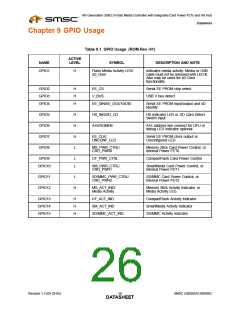
Chapter 9 GPIO Usage
Table 9.1 GPIO Usage (ROM Rev -01)
ACTIVE
LEVEL
NAME
SYMBOL
DESCRIPTION AND NOTE
GPIO1
H
Flash Media Activity LED/
xD_Door
Indicates media activity. Media or USB
cable must not be removed with LED lit.
Also may be used for xD Door
functionality
GPIO2
GPIO3
GPIO4
H
H
H
EE_CS
Serial EE PROM chip select
USB V bus detect
V_BUS
EE_DIN/EE_DOUT/xDID
Serial EE PROM input/output and xD
Identify
GPIO5
GPIO6
GPIO7
GPIO8
H
H
H
L
HS_IND/SD_CD
A16/ROMEN
HS Indicator LED or SD Card Detect
Switch input
A16 address line connect for DFU or
debug LED indicator optional.
EE_CLK/
Serial EE PROM clock output or
Unconfigured LED.
UNCONF_LED
MS_PWR_CTRL/
CRD_PWR0
Memory Stick Card Power Control, or
Internal Power FET0.
GPIO9
L
L
CF_PWR_CTRL
CompactFlash Card Power Control
GPIO10
SM_PWR_CTRL/
CRD_PWR1
SmartMedia Card Power Control, or
Internal Power FET1.
GPIO11
GPIO12
L
SD/MMC_PWR_CTRL/
CRD_PWR2
SD/MMC Card Power Control, or
Internal Power FET2.
H
MS_ACT_IND/
Media Activity
Memory Stick Activity Indicator, or
Media Activity LED.
GPIO13
GPIO14
GPIO15
H
H
H
CF_ACT_IND
CompactFlash Activity Indicator
SmartMedia Activity Indicator
SD/MMC Activity Indicator
SM_ACT_IND
SD/MMC_ACT_IND
Revision 1.3 (05-25-05)
SMSC USB2601/USB2602
DATA2S6HEET

 SMSC [ SMSC CORPORATION ]