4th Generation USB2.0 Flash Media Controller with Integrated Card Power FETs and HS Hub
Datasheet
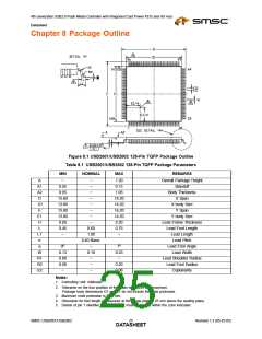
Chapter 8 Package Outline
Figure 8.1 USB2601/USB2602 128-Pin TQFP Package Outline
Table 8.1 USB2601/USB2602 128-Pin TQFP Package Parameters
MIN
NOMINAL
MAX
REMARKS
A
A1
A2
D
D1
E
E1
H
L
L1
e
q
W
R1
R2
ccc
~
~
~
~
~
~
~
~
~
1.20
0.15
1.05
16.20
14.20
16.20
14.20
0.20
0.75
~
Overall Package Height
Standoff
0.05
0.95
15.80
13.80
15.80
13.80
0.09
0.45
~
Body Thickness
X Span
X body Size
Y Span
Y body Size
Lead Frame Thickness
Lead Foot Length
Lead Length
0.60
1.00
0.40 Basic
Lead Pitch
Lead Foot Angle
Lead Width
0o
0.13
0.08
0.08
~
~
0.18
~
~
~
7o
0.23
~
0.20
0.08
Lead Shoulder Radius
Lead Foot Radius
Coplanarity
Notes:
1. Controlling Unit: millimeter.
2. Tolerance on the true position of the leads is ± 0.035 mm maximum.
Package body dimensions D1 and E1 do not include the mold protrusion.
3. Maximum mold protrusion is 0.25 mm.
4. Dimension for foot length L measured at the gauge plane 0.25 mm above the seating plane.
5. Details of pin 1 identifier are optional but must be located within the zone indicated.
SMSC USB2601/USB2602
Revision 1.3 (05-25-05)
DATA2S5HEET

 SMSC [ SMSC CORPORATION ]