Advanced I/O Controller with Motherboard GLUE Logic
Datasheet
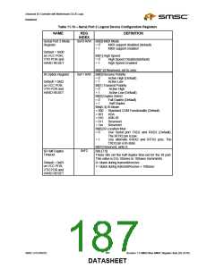
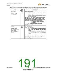
Table 11.10 – Serial Port 2 Logical Device Configuration Registers
NAME
REG
DEFINITION
INDEX
Serial Port 2 Mode
Register
0xF0 R/W Bit[0] MIDI Mode
= 0
= 1
MIDI support disabled (default)
MIDI support enabled
Default = 0x00
on VCC POR,
VTR POR and
HARD RESET
Bit[1] High Speed
= 0
= 1
High Speed Disabled(default)
High Speed Enabled
Bit[7:2] Reserved, set to zero
0xF1 R/W Bit[0] Receive Polarity
= 0 Active High (Default)
= 1 Active Low
IR Option Register
Default = 0x02
on VCC POR,
VTR POR and
HARD RESET
Bit[1] Transmit Polarity
= 0
= 1
Active High
Active Low (Default)
Bit[2] Duplex Select
= 0
= 1
Full Duplex (Default)
Half Duplex
Bits[5:3] IR Mode
= 000
= 001
= 010
= 011
= 1xx
Standard COM Functionality (Default)
IrDA
ASK-IR
Reserved
Reserved
Bit[6] IR Location Mux
= 0
Use Serial port TXD2 and RXD2 (Default).
The IRTX2 pin is low.
= 1
Use alternate IRRX2 and IRTX2 pins. The
TXD2 pin is tri-state.
Bit[7] Reserved, write 0.
Bits [7:0]
0xF2
IR Half Duplex
Timeout
These bits set the half duplex time-out for the IR port.
This value is 0 to 10msec in 100usec increments.
0= blank during transmit/receive
1= blank during transmit/receive + 100usec
. . .
Default = 0x03
on VCC POR,
VTR POR and
HARD RESET
SMSC LPC47M182
187
Revision 1.8 SMSC/Non-SMSC Register Sets (02-24-05)
DATASHEET

 SMSC [ SMSC CORPORATION ]