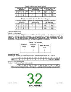
Table 3 − Internal 2 Drive Decode - Normal
DIGITAL OUTPUT
DRIVE SELECT OUTPUTS
(ACTIVE LOW)
MOTOR ON OUTPUTS
(ACTIVE LOW)
REGISTER
Bit 5 Bit 4 Bit1 Bit 0
nDS1
nDS0
nMTR1
nMTR0
nBIT 4
nBIT 4
nBIT 4
X
1
0
1
X
0
0
0
0
1
X
1
0
1
0
1
1
nBIT 5
nBIT 5
nBIT 5
X
Table 4 − Internal 2 Drive Decode - Drives 0 and 1 Swapped
DIGITAL OUTPUT
REGISTER
DRIVE SELECT OUTPUTS
(ACTIVE LOW)
MOTOR ON OUTPUTS
(ACTIVE LOW)
Bit 5 Bit 4 Bit1 Bit 0
nDS1
nDS0
nMTR1
nBIT 4
nBIT 4
nBIT 4
nMTR0
nBIT 5
nBIT 5
nBIT 5
X
1
0
1
X
0
0
0
0
1
X
0
1
1
1
0
1
X
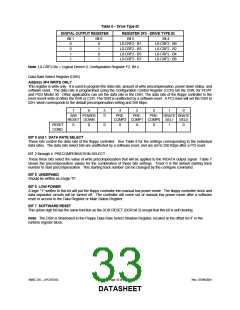
Tape Drive Register (TDR)
Address 3F3 READ/WRITE
The Tape Drive Register (TDR) is included for 82077 software compatibility and allows the user to assign tape
support to a particular drive during initialization. Any future references to that drive automatically invokes tape
support. The TDR Tape Select bits TDR.[1:0] determine the tape drive number. Table 5 illustrates the Tape Select
Bit encoding. Note that drive 0 is the boot device and cannot be assigned tape support. The remaining Tape Drive
Register bits TDR.[7:2] are tristated when read. The TDR is unaffected by a software reset.
Table 5 − Tape Select Bits
TAPE SEL1
TAPE SEL0
DRIVE SELECTED
(TDR.1)
(TDR.0)
0
0
1
1
0
1
0
1
None
1
2
3
Normal Floppy Mode
Normal mode. Register 3F3 contains only bits 0 and 1. When this register is read, bits 2 - 7 are ‘0’.
DB7
0
DB6
0
DB5
0
DB4
0
DB3
0
DB2
0
DB1
DB0
REG 3F3
tape sel1 tape sel0
Enhanced Floppy Mode 2 (OS2)
Register 3F3 for Enhanced Floppy Mode 2 operation.
DB7
DB6
DB5
DB4
DB3
DB2
DB1
DB0
REG 3F3 Reserved Reserved
Drive Type ID
Floppy Boot Drive
tape sel1 tape sel0
SMSC DS – LPC47S45x
Page 32 of 259
Rev. 07/09/2001
DATASHEET

 SMSC [ SMSC CORPORATION ]