Control Register
Overview
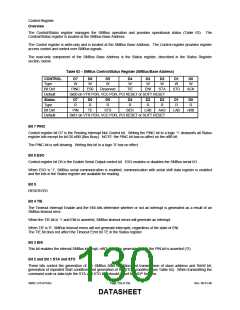
The Control/Status register manages the SMBus operation and provides operational status (Table 63). The
Control/Status register is located at the SMBus Base Address.
The Control register is write-only and is located at the SMBus Base Address. The Control register provides register
access control and control over SMBus signals.
The read-only component of the SMBus Base Address is the Status register, described in the Status Register
section, below.
Table 63 − SMBus Control/Status Register (SMBus/Base Address)
CONTROL
Type
D7
W
D6
W
D5
W
D4
W
D3
W
D2
W
D1
W
D0
W
Bit Def
PINC
ES0
Reserved
TIE
ENI
STA
STO
ACK
Default
0x00 on VTR POR, VCC POR, PCI RESET or SOFT RESET
Status
Type
D7
R
D6
R
D5
R
D4
R
D3
R
D2
R
D1
R
D0
R
Bit Def
Default
PIN
TE
STS
BER
LRB
AAS
LAB
nBB
0x81 on VTR POR, VCC POR, PCI RESET or SOFT RESET
Bit 7 PINC
Control register bit D7 is the Pending Interrupt Not Control bit. Writing the PINC bit to a logic ‘1’ deasserts all Status
register bits except for bit D0 nBB (Bus Busy). NOTE: the PINC bit has no affect on the nBB bit.
The PINC bit is self-clearing. Writing this bit to a logic ‘0’ has no effect.
Bit 6 ESO
Control register bit D6 is the Enable Serial Output control bit. ESO enables or disables the SMBus serial I/O.
When ESO is ‘1’, SMBus serial communication is enabled; communication with serial shift data register is enabled
and the bits in the Status register are available for reading.
Bit 5
RESERVED
Bit 4 TIE
The Timeout Interrupt Enable and the ENI bits determine whether or not an interrupt is generated as a result of an
SMBus timeout error.
When the TIE bit is ‘1’ and ENI is asserted, SMBus timeout errors will generate an interrupt.
When TIE is ‘0’, SMBus timeout errors will not generate interrupts, regardless of the state of ENI.
The TIE bit does not affect the Timeout Error bit TE in the Status register.
Bit 3 ENI
This bit enables the internal SMBus interrupt, nINT, which is generated when the PIN bit is asserted (‘0’).
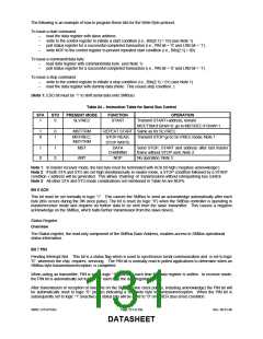
Bit 2 and Bit 1 STA and STO
These bits control the generation of the SMBus Start condition and transmission of slave address and R/nW bit,
generation of repeated Start condition, and generation of the STOP condition (see Table 64). When transmitting the
command code or data byte the STA and STO bits should bit set for NOP function.
SMSC LPC47S45x
Page 130 of 259
Rev. 06-01-06
DATASHEET

 SMSC [ SMSC CORPORATION ]