If the fan is functioning, a value is preloaded into the counter on the rising edge of the Fan Tachometer input. The
counter counts the number of clock pulses generated for the duration of one Fan Tachometer input pulse. This value
(Count) is then stored into the FAN_TACH register. If the fan is operating at 70% (or less) of the maximum capacity,
the Count value will be greater than or equal to 192 and thereby generate a PME# signal. To ensure the FAN_TACH
register has been updated if the fan suddenly seizes, a second PME is generated when the counter reaches 0xFF
and the FAN_TACH register is latched again. The FAN_TACH register will remain at this value until another Fan
Tachometer input pulse is received.
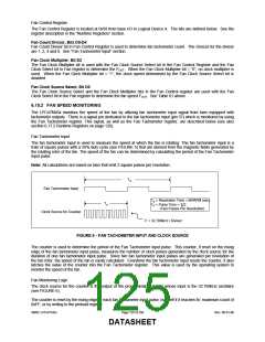
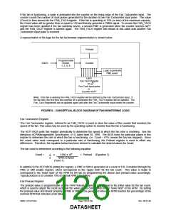
A representation of the logic for the fan tachometer implementation is shown below.
Preload
Programmable
32kHz
Divider
Counter
1, 2, 4, 8
Logic to generate
PME event
Latch
Fan Tach Register
on
Fan Tach input pulse
or
Counter=0xFF
Note: If the fan is working the FAN_TACH register will be latched by the Fan Tachometer input. If
the fan fails, the first time the overflow bit is generated the FAN_TACH register will be updated. The
Fan_Tach Registerwill not be updated again until after the Fan Tachometer input resets the counter.
FIGURE 6 − CONCEPTUAL BLOCK DIAGRAM OF FAN MONITORING LOGIC
Fan Tachometer Register
The Fan Tachometer register, referred to as FAN_TACH, is used to store the value of the counter that monitors the
speed of the fan. This value may be used by the operating system to monitor how the fan is functioning.
The ACPI BIOS polls this register periodically to determine the speed at which the fan rotor is revolving. See the
Metalious ACPI/Manageability Specification, v1.0, dated April 30, 1999. The BIOS looks for particular values in this
register to determine the rate at which the fan is functioning. (i.e. Count = FFh; means the fan has stopped). Since
the count value must correspond to a particular rate of functioning, the Preload register is used to offset any
differences. Therefore, the equation below has been derived to calculate the desired values for Count.
The fan count is determined according to the following equation:
Count =
1
2
x
1.966 x 106
RPM x Divisor
+ Preload (Equation 1)
(Term 1)
In addition to the ACPI BIOS polling the register, a PME or SMI is generated at a count of 192, if enabled through the
PME or SMI enable register, which corresponds to the “upper limit” for the fan count. This value is made to
correspond to the “lower limit” of the RPM for the fan by programming the divisor and preload value accordingly.
Typical practice is to consider 70% of normal RPM a fan failure.
Fan Preload Register
The preload value is programmable via the FAN Preload Register. The preload is the initial value for the fan count,
which is used to adjust the count such that the value of 192 corresponds to the “lower limit” of the RPM. By setting
the preload value and divisor properly, a PME or SMI will be generated when the RPM reaches the percentage of the
nominal RPM that indicates a fan failure.
SMSC LPC47S45x
Page 126 of 259
Rev. 06-01-06
DATASHEET

 SMSC [ SMSC CORPORATION ]