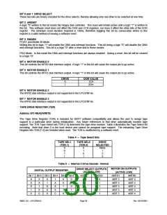
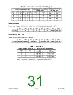
Table 6 – Internal 2 Drive Decode - Drives 0 and 1 Swapped
MOTOR ON OUTPUTS
(ACTIVE LOW)
DRIVE SELECT OUTPUTS
(ACTIVE LOW)
DIGITAL OUTPUT REGISTER
Bit 7 Bit 6 Bit 5 Bit 4 Bit1 Bit 0
nDS1
nDS0
nMTR1
nMTR0
nBIT 5
nBIT 5
nBIT 5
nBIT 5
nBIT 5
X
X
X
1
X
X
1
X
1
X
X
0
1
X
X
X
0
0
0
1
1
X
0
1
0
1
X
0
1
1
1
1
1
0
1
1
1
nBIT 4
nBIT 4
nBIT 4
nBIT 4
nBIT 4
X
0
0
Normal Floppy Mode
Normal mode. Register 3F3 contains only bits 0 and 1. When this register is read, bits 2 - 7 are ‘0’.
DB7
DB6
DB5
DB4
DB3
DB2
DB1
DB0
REG 3F3
0
0
0
0
0
0
tape sel1 tape sel0
Enhanced Floppy Mode 2 (OS2)
Register 3F3 for Enhanced Floppy Mode 2 operation.
DB7
DB6
DB5
DB4
DB3
DB2
DB1
DB0
REG 3F3 Reserved Reserved
Drive Type ID
Floppy Boot Drive
tape sel1 tape sel0
Table 7 – Drive Type ID
DIGITAL OUTPUT REGISTER REGISTER 3F3 - DRIVE TYPE ID
Bit 1
Bit 0
Bit 5
Bit 4
0
0
1
1
0
1
0
1
L0-CRF2 - B1
L0-CRF2 - B3
L0-CRF2 - B5
L0-CRF2 - B7
L0-CRF2 - B0
L0-CRF2 - B2
L0-CRF2 - B4
L0-CRF2 - B6
Note: L0-CRF2-Bx = Logical Device 0, Configuration Register F2, Bit x.
SMSC DS – LPC47M14X
Page 31
Rev. 03/19/2001

 SMSC [ SMSC CORPORATION ]