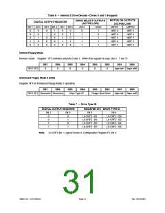
6.5.1
FDC Internal Registers
The Floppy Disk Controller contains eight internal registers, which facilitate the interfacing between the host
microprocessor and the disk drive. Table 3 shows the addresses required to access these registers. Registers other
than the ones shown are not supported. The rest of the description assumes that the primary addresses have been
selected.
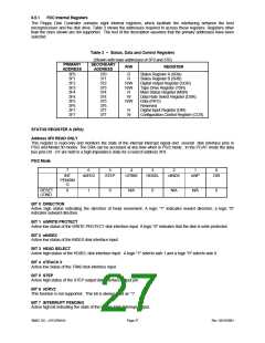
Table 3 – Status, Data and Control Registers
(Shown with base addresses of 3F0 and 370)
PRIMARY
ADDRESS
SECONDARY
R/W
REGISTER
ADDRESS
3F0
3F1
3F2
3F3
3F4
3F4
3F5
3F6
3F7
3F7
370
371
372
373
374
374
375
376
377
377
R
R
Status Register A (SRA)
Status Register B (SRB)
Digital Output Register (DOR)
Tape Drive Register (TSR)
Main Status Register (MSR)
Data Rate Select Register (DSR)
Data (FIFO)
R/W
R/W
R
W
R/W
Reserved
R
Digital Input Register (DIR)
Configuration Control Register (CCR)
W
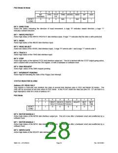
STATUS REGISTER A (SRA)
Address 3F0 READ ONLY
This register is read-only and monitors the state of the internal interrupt signal and several disk interface pins in
PS/2 and Model 30 modes. The SRA can be accessed at any time when in PS/2 mode. In the PC/AT mode the data
bus pins D0 - D7 are held in a high impedance state for a read of address 3F0.
PS/2 Mode
7
6
5
4
3
2
1
nWP
0
DIR
INT
PENDIN
G
nDRV2
STEP
nTRK0
HDSEL
nINDX
RESET
COND.
0
1
0
N/A
0
N/A
N/A
0
BIT 0 DIRECTION
Active high status indicating the direction of head movement. A logic "1" indicates inward direction; a logic "0"
indicates outward direction.
BIT 1 nWRITE PROTECT
Active low status of the WRITE PROTECT disk interface input. A logic "0" indicates that the disk is write protected.
BIT 2 nINDEX
Active low status of the INDEX disk interface input.
BIT 3 HEAD SELECT
Active high status of the HDSEL disk interface input. A logic "1" selects side 1 and a logic "0" selects side 0.
BIT 4 nTRACK 0
Active low status of the TRK0 disk interface input.
BIT 5 STEP
Active high status of the STEP output disk interface output pin.
BIT 6 nDRV2
This function is not supported. This bit is always read as “1”.
BIT 7 INTERRUPT PENDING
Active high bit indicating the state of the Floppy Disk Interrupt output.
SMSC DS – LPC47M14X
Page 27
Rev. 03/19/2001

 SMSC [ SMSC CORPORATION ]