ports. The internal 24MHz driven PLL (and the 48MHz in the Hub Block) will be started to complete the
Resume.
6.4.1
USB Downstream Port Selection
The LPC47M14x USB Hub has the ability to program, via BIOS, control register access or through external PIN
strapping options, the number of Down Stream Ports that are available to the User. There is also a “Pin Strapping”
option that will allow the board designer the ability to define the number of down stream ports that will be active via
during USB_PWR POR.
The LPC47M120 USB Hub block will make the following changes to its external signals and device class response
parameters:
1) All related input and output signals such as the associated Over-current sense pins (nUSBOC[x]) and Power
Enable (nPWREN[x]) pin are also disabled.
2) The USB Down Stream Port nUSBOC[x] input pin can be a NC (No Connect) pin or tied High (1). For EMI and
reduced Noise sensitivity, it is recommended that the pin be tied High (1).
3) The Power Enable (nPWREN[x]) pin will be forced low (0). For EMI and reduced Noise sensitivity, it is
recommended that the pin be tied High (1).
4) The associated PDx+ and PDx- pins will not be active can be a NC (No Connect) pin). For EMI and reduced
Noise sensitivity, it is recommended that the pin be tied High (1).
5) All Hub Device Class return descriptor must respond with the appropriate information relating to the number of
ports that are currently selected by the Strap Pins or control bits in the register described in Table 76
–
HubControl_1 Register Definition, shown on page 171, below, describes what fields now need to be
programmed bas on the number of enabled ports.
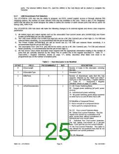
Table 2 – Hub Descriptor to be Modified
OFFSET
FIELD
bDescLength
PROGRAMMABLE
SIZE
1
DESCRIPTION
Number of bytes in this descriptor, including
0
this byte.
1
2
bDescriptorType
bNbrPorts
1
1
Descriptor Type
X
Number of downstream ports that this hub
supports. Selected by the “Strp0 and nStrp1”
input pins or the HubControl_1 register defined
in
Table 76
–
HubControl_1 Register
Definition, shown on page 171, below.
D1..D0: Power Switching Mode
3
wHubCharacteristics
2
00 - Ganged power switching (all ports’ power
at once)
01 - Individual port power switching
1X - No power switching (ports always powered
on when hub is on and off when hub is off).
D2:Identifies a Compound Device
0 - Hub is not part of a compound device
1 - Hub is part of a compound device
D4..D3: Over-current Protection Mode
00 - Global Over-current Protection. The hub
reports over-current as a summation of all
ports’ current draw, without a breakdown of
individual port over-current status.
01 - Individual Port Over-current protection.
The hub reports over-current on a per-port
basis. Each port has an over-current indicator.
1X -No Over-Current Protection. This option is
only allowed for bus-powered hubs that do not
implement over-current protection.
D15..D5: Reserved
SMSC DS – LPC47M14X
Page 25
Rev. 03/19/2001

 SMSC [ SMSC CORPORATION ]