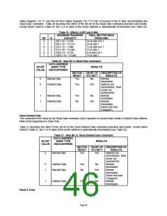
second occurrence of a pulse on the nINDEX pin, it then sets the IC code in Status Register 0 to "01" (abnormal
termination), sets the MA bit in Status Register 1 to "1", and terminates the command.
The following commands will generate an interrupt upon completion. They do not return any result bytes. It is highly
recommended that control commands be followed by the Sense Interrupt Status command. Otherwise, valuable
interrupt status information will be lost.
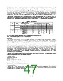
Recalibrate
This command causes the read/write head within the FDC to retract to the track 0 position. The FDC clears the contents
of the PCN counter and checks the status of the nTRK0 pin from the FDD. As long as the nTRK0 pin is low, the DIR pin
remains 0 and step pulses are issued. When the nTRK0 pin goes high, the SE bit in Status Register 0 is set to "1" and
the command is terminated. If the nTRK0 pin is still low after 79 step pulses have been issued, the FDC sets the SE and
the EC bits of Status Register 0 to "1" and terminates the command. Disks capable of handling more than 80 tracks per
side may require more than one Recalibrate command to return the head back to physical Track 0.
The Recalibrate command does not have a result phase. The Sense Interrupt Status command must be issued after the
Recalibrate command to effectively terminate it and to provide verification of the head position (PCN). During the
command phase of the recalibrate operation, the FDC is in the BUSY state, but during the execution phase it is in a
NON-BUSY state. At this time, another Recalibrate command may be issued, and in this manner parallel Recalibrate
operations may be done on up to four drives at once. Upon power up, the software must issue a Recalibrate command
to properly initialize all drives and the controller.
Seek
The read/write head within the drive is moved from track to track under the control of the Seek command. The FDC
compares the PCN, which is the current head position, with the NCN and performs the following operation if there is a
difference:
PCN < NCN:
PCN > NCN:
Direction signal to drive set to "1" (step in) and issues step pulses.
Direction signal to drive set to "0" (step out) and issues step pulses.
The rate at which step pulses are issued is controlled by SRT (Stepping Rate Time) in the Specify command. After each
step pulse is issued, NCN is compared against PCN, and when NCN = PCN the SE bit in Status Register 0 is set to "1"
and the command is terminated. During the command phase of the seek or recalibrate operation, the FDC is in the
BUSY state, but during the execution phase it is in the NON-BUSY state. At this time, another Seek or Recalibrate
command may be issued, and in this manner, parallel seek operations may be done on up to four drives at once.
Note that if implied seek is not enabled, the read and write commands should be preceded by:
1) Seek command - Step to the proper track
2) Sense Interrupt Status command - Terminate the Seek command
3) Read ID - Verify head is on proper track
4) Issue Read/Write command.
The Seek command does not have a result phase. Therefore, it is highly recommended that the Sense Interrupt Status
command is issued after the Seek command to terminate it and to provide verification of the head position (PCN). The
H bit (Head Address) in ST0 will always return to a "0". When exiting POWERDOWN mode, the FDC clears the PCN
value and the status information to zero. Prior to issuing the POWERDOWN command, it is highly recommended that
the user service all pending interrupts through the Sense Interrupt Status command.
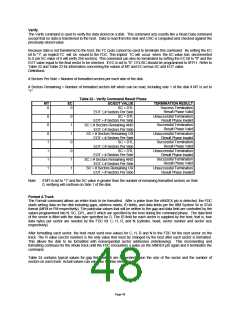
Sense Interrupt Status
An interrupt signal is generated by the FDC for one of the following reasons:
1. Upon entering the Result Phase of:
a. Read Data command
b. Read A Track command
c. Read ID command
d. Read Deleted Data command
e. Write Data command
f. Format A Track command
g. Write Deleted Data command
h. Verify command
Page 50

 SMSC [ SMSC CORPORATION ]