This command is similar to the Read Data command except that the entire data field is read continuously from each of
the sectors of a track. Immediately after encountering a pulse on the nINDEX pin, the FDC starts to read all data fields
on the track as continuous blocks of data without regard to logical sector numbers. If the FDC finds an error in the ID or
DATA CRC check bytes, it continues to read data from the track and sets the appropriate error bits at the end of the
command. The FDC compares the ID information read from each sector with the specified value in the command and
sets the ND flag of Status Register 1 to a “1” if there no comparison. Multi-track or skip operations are not allowed with
this command. The MT and SK bits (bits D7 and D5 of the first command byte respectively) should always be set to "0".
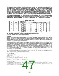
This command terminates when the EOT specified number of sectors has not been read. If the FDC does not find an ID
Address Mark on the diskette after the second occurrence of a pulse on the INDEX pin, then it sets the IC code in Status
Register 0 to "01" (abnormal termination), sets the MA bit in Status Register 1 to "1", and terminates the command.
Table 22 - Result Phase
FINAL SECTOR
MT
HEAD
TRANSFERRED TO
ID INFORMATION AT RESULT PHASE
HOST
C
H
R
N
0
0
1
0
1
Less than EOT
Equal to EOT
Less than EOT
Equal to EOT
Less than EOT
Equal to EOT
Less than EOT
Equal to EOT
NC
C + 1
NC
C + 1
NC
NC
NC
NC
NC
NC
NC
LSB
NC
LSB
R + 1
01
R + 1
01
R + 1
01
R + 1
01
NC
NC
NC
NC
NC
NC
NC
NC
1
NC
C + 1
NC: No Change, the same value as the one at the beginning of command execution.
LSB: Least Significant Bit, the LSB of H is complemented.
Write Data
After the Write Data command has been issued, the FDC loads the head (if it is in the unloaded state), waits the
specified head load time if unloaded (defined in the Specify command), and begins reading ID fields. When the sector
address read from the diskette matches the sector address specified in the command, the FDC reads the data from the
host via the FIFO and writes it to the sector's data field.
After writing data into the current sector, the FDC computes the CRC value and writes it into the CRC field at the end of
the sector transfer. The Sector Number stored in "R" is incremented by one, and the FDC continues writing to the next
data field. The FDC continues this "Multi-Sector Write Operation". Upon receipt of a terminal count signal or if a FIFO
over/under run occurs while a data field is being written, then the remainder of the data field is filled with zeros. The
FDC reads the ID field of each sector and checks the CRC bytes. If it detects a CRC error in one of the ID fields, it sets
the IC code in Status Register 0 to "01" (abnormal termination), sets the DE bit of Status Register 1 to "1", and
terminates the Write Data command.
The Write Data command operates in much the same manner as the Read Data command. The following items are the
same. Please refer to the Read Data Command for details:
Transfer Capacity
EN (End of Cylinder) bit
ND (No Data) bit
Head Load, Unload Time Interval
ID information when the host terminates the command
Definition of DTL when N = 0 and when N does not = 0
Write Deleted Data
This command is almost the same as the Write Data command except that a Deleted Data Address Mark is written at
the beginning of the Data Field instead of the normal Data Address Mark. This command is typically used to mark a bad
sector containing an error on the floppy disk.
Page 47

 SMSC [ SMSC CORPORATION ]