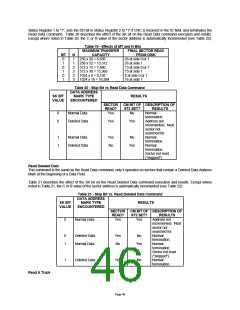
Status Register 1 to "1", sets the DD bit in Status Register 2 to "1" if CRC is incorrect in the ID field, and terminates the
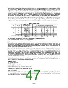
Read Data Command. Table 20 describes the effect of the SK bit on the Read Data command execution and results.
Except where noted in Table 20, the C or R value of the sector address is automatically incremented (see Table 22).
Table 19 - Effects of MT and N Bits
MAXIMUM TRANSFER
CAPACITY
FINAL SECTOR READ
FROM DISK
26 at side 0 or 1
26 at side 1
15 at side 0 or 1
15 at side 1
8 at side 0 or 1
16 at side 1
MT
0
1
0
1
N
1
1
2
2
3
3
256 x 26 = 6,656
256 x 52 = 13,312
512 x 15 = 7,680
512 x 30 = 15,360
1024 x 8 = 8,192
1024 x 16 = 16,384
0
1
Table 20 - Skip Bit vs Read Data Command
DATA ADDRESS
SK BIT
MARK TYPE
RESULTS
VALUE
ENCOUNTERED
SECTOR CM BIT OF DESCRIPTION OF
READ?
ST2 SET?
RESULTS
0
0
Normal Data
Deleted Data
Yes
No
Normal
termination.
Address not
incremented. Next
sector not
Yes
Yes
searched for.
Normal
termination.
Normal
1
1
Normal Data
Deleted Data
Yes
No
No
Yes
termination.
Sector not read
("skipped").
Read Deleted Data
This command is the same as the Read Data command, only it operates on sectors that contain a Deleted Data Address
Mark at the beginning of a Data Field.
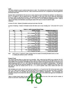
Table 21 describes the effect of the SK bit on the Read Deleted Data command execution and results. Except where
noted in Table 21, the C or R value of the sector address is automatically incremented (see Table 22).
Table 21 - Skip Bit vs. Read Deleted Data Command
DATA ADDRESS
SK BIT
VALUE
MARK TYPE
ENCOUNTERED
RESULTS
SECTOR CM BIT OF DESCRIPTION OF
READ?
ST2 SET?
RESULTS
0
Normal Data
Yes
Yes
Address not
incremented. Next
sector not
searched for.
Normal
termination.
Normal
0
1
Deleted Data
Normal Data
Yes
No
No
Yes
termination.
Sector not read
("skipped").
Normal
1
Deleted Data
Yes
No
termination.
Read A Track
Page 46

 SMSC [ SMSC CORPORATION ]