Verify
The Verify command is used to verify the data stored on a disk. This command acts exactly like a Read Data command
except that no data is transferred to the host. Data is read from the disk and CRC is computed and checked against the
previously-stored value.
Because data is not transferred to the host, the TC cycle cannot be used to terminate this command. By setting the EC
bit to "1", an implicit TC will be issued to the FDC. This implicit TC will occur when the SC value has decremented
to 0 (an SC value of 0 will verify 256 sectors). This command can also be terminated by setting the EC bit to "0" and the
EOT value equal to the final sector to be checked. If EC is set to "0", DTL/SC should be programmed to 0FFH. Refer to
Table 22 and Table 23 for information concerning the values of MT and EC versus SC and EOT value.
Definitions:
# Sectors Per Side = Number of formatted sectors per each side of the disk.
# Sectors Remaining = Number of formatted sectors left which can be read, including side 1 of the disk if MT is set to
"1".
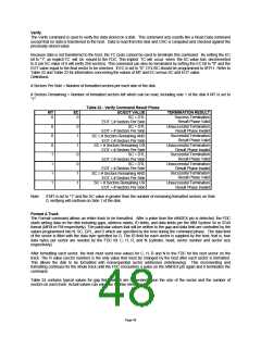
Table 23 - Verify Command Result Phase
MT
0
EC
0
SC/EOT VALUE
SC = DTL
EOT ≤ # Sectors Per Side
SC = DTL
TERMINATION RESULT
Success Termination
Result Phase Valid
Unsuccessful Termination
Result Phase Invalid
Successful Termination
Result Phase Valid
0
0
0
1
EOT > # Sectors Per Side
SC ≤ # Sectors Remaining AND
EOT ≤ # Sectors Per Side
SC > # Sectors Remaining OR
EOT > # Sectors Per Side
SC = DTL
0
1
1
1
1
0
0
1
Unsuccessful Termination
Result Phase Invalid
Successful Termination
Result Phase Valid
Unsuccessful Termination
Result Phase Invalid
Successful Termination
Result Phase Valid
EOT ≤ # Sectors Per Side
SC = DTL
EOT > # Sectors Per Side
SC ≤ # Sectors Remaining AND
EOT ≤ # Sectors Per Side
1
1
SC > # Sectors Remaining OR
EOT > # Sectors Per Side
Unsuccessful Termination
Result Phase Invalid
Note:
If MT is set to "1" and the SC value is greater than the number of remaining formatted sectors on Side
0, verifying will continue on Side 1 of the disk.
Format A Track
The Format command allows an entire track to be formatted. After a pulse from the nINDEX pin is detected, the FDC
starts writing data on the disk including gaps, address marks, ID fields, and data fields per the IBM System 34 or 3740
format (MFM or FM respectively). The particular values that will be written to the gap and data field are controlled by the
values programmed into N, SC, GPL, and D which are specified by the host during the command phase. The data field
of the sector is filled with the data byte specified by D. The ID field for each sector is supplied by the host; that is, four
data bytes per sector are needed by the FDC for C, H, R, and N (cylinder, head, sector number and sector size
respectively).
After formatting each sector, the host must send new values for C, H, R and N to the FDC for the next sector on the
track. The R value (sector number) is the only value that must be changed by the host after each sector is formatted.
This allows the disk to be formatted with nonsequential sector addresses (interleaving). This incrementing and
formatting continues for the whole track until the FDC encounters a pulse on the nINDEX pin again and it terminates the
command.
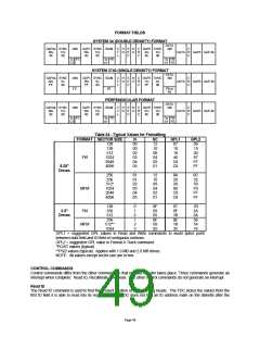
Table 24 contains typical values for gap fields which are dependent upon the size of the sector and the number of
sectors on each track. Actual values can vary due to drive electronics.
Page 48

 SMSC [ SMSC CORPORATION ]