Any command issued will use the current PCN value except for the Recalibrate command, which only looks for the
TRACK0 signal. Recalibrate will return an error if the head is farther than 79 due to its limitation of issuing a maximum
of 80 step pulses. The user simply needs to issue a second Recalibrate command. The Seek command and implied
seeks will function correctly within the 44 (D) track (299-255) area of the "extended track area". It is the user's
responsibility not to issue a new track position that will exceed the maximum track that is present in the extended area.
To return to the standard floppy range (0-255) of tracks, a Relative Seek should be issued to cross the track 255
boundary.
A Relative Seek can be used instead of the normal Seek, but the host is required to calculate the difference between the
current head location and the new (target) head location. This may require the host to issue a Read ID command to
ensure that the head is physically on the track that software assumes it to be. Different FDC commands will return
different cylinder results which may be difficult to keep track of with software without the Read ID command.
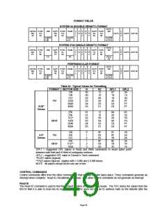
Perpendicular Mode
The Perpendicular Mode command should be issued prior to executing Read/Write/Format commands that access a
disk drive with perpendicular recording capability. With this command, the length of the Gap2 field and VCO enable
timing can be altered to accommodate the unique requirements of these drives. Table 27 describes the effects of the
WGATE and GAP bits for the Perpendicular Mode command. Upon a reset, the FDC will default to the conventional
mode (WGATE = 0, GAP = 0).
Selection of the 500 Kbps and 1 Mbps perpendicular modes is independent of the actual data rate selected in the Data
Rate Select Register. The user must ensure that these two data rates remain consistent.
The Gap2 and VCO timing requirements for perpendicular recording type drives are dictated by the design of the
read/write head. In the design of this head, a pre-erase head precedes the normal read/write head by a distance of 200
micrometers. This works out to about 38 bytes at a 1 Mbps recording density. Whenever the write head is enabled by
the Write Gate signal, the pre-erase head is also activated at the same time. Thus, when the write head is initially turned
on, flux transitions recorded on the media for the first 38 bytes will not be preconditioned with the pre-erase head since it
has not yet been activated. To accommodate this head activation and deactivation time, the Gap2 field is expanded to a
length of 41 bytes. The format field shown on Page 58 illustrates the change in the Gap2 field size for the
perpendicular format.
On the read back by the FDC, the controller must begin synchronization at the beginning of the sync field. For the
conventional mode, the internal PLL VCO is enabled (VCOEN) approximately 24 bytes from the start of the Gap2 field.
But, when the controller operates in the 1 Mbps perpendicular mode (WGATE = 1, GAP = 1), VCOEN goes active after
43 bytes to accommodate the increased Gap2 field size. For both cases, and approximate two-byte cushion is
maintained from the beginning of the sync field for the purposes of avoiding write splices in the presence of motor speed
variation.
For the Write Data case, the FDC activates Write Gate at the beginning of the sync field under the conventional mode.
The controller then writes a new sync field, data address mark, data field, and CRC. With the pre-erase head of the
perpendicular drive, the write head must be activated in the Gap2 field to insure a proper write of the new sync field. For
the 1 Mbps perpendicular mode (WGATE = 1, GAP = 1), 38 bytes will be written in the Gap2 space. Since the bit density
is proportional to the data rate, 19 bytes will be written in the Gap2 field for the 500 Kbps perpendicular mode (WGATE =
1, GAP =0).
It should be noted that none of the alterations in Gap2 size, VCO timing, or Write Gate timing affect normal program
flow. The information provided here is just for background purposes and is not needed for normal operation. Once the
Perpendicular Mode command is invoked, FDC software behavior from the user standpoint is unchanged.
The perpendicular mode command is enhanced to allow specific drives to be designated Perpendicular recording drives.
This enhancement allows data transfers between Conventional and Perpendicular drives without having to issue
Perpendicular mode commands between the accesses of the different drive types, nor having to change write pre-
compensation values.
When both GAP and WGATE bits of the PERPENDICULAR MODE COMMAND are both programmed to "0"
(Conventional mode), then D0, D1, D2, D3, and D4 can be programmed independently to "1" for that drive to be set
automatically to Perpendicular mode. In this mode the following set of conditions also apply:
1. The GAP2 written to a perpendicular drive during a write operation will depend upon the programmed data rate.
Page 53

 SMSC [ SMSC CORPORATION ]