Three Port 10/100 Managed Ethernet Switch with MII
Datasheet
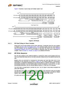
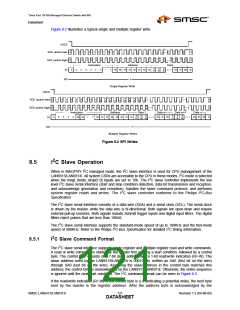
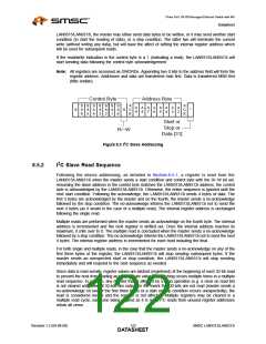
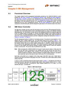
Figure 8.2 illustrates a typical single and multiple register write.
nSCS
1
0
1
1
1
2
1
3
1
4
1
5
1
6
1
7
1
8
1
9
4
5
4
6
4
7
4
8
X
X
1
2
3
4
5
6
7
8
9
X
X
...
SCK (active low)
1
0
1
1
1
2
1
3
1
4
1
5
1
6
1
7
1
8
1
4
5
4
6
4
7
4
8
1
2
3
4
5
6
7
8
9
...
SCK (active high)
9
Instruction
Address
Data
D
31
D
30
D
29
...
X
0
0
0
0
0
0
1
1
A9 A8 A7 A6 A5 A4 A3 A2
D2 D1 D0
X
SI
Z
SO
Single Register Write
nSCS
1
0
1
1
1
2
1
3
1
4
1
5
1
6
1
7
1
8
1
9
X
X
1
2
3
4
5
6
7
8
9
...
...
X
X
SCK (active low)
1
0
1
1
1
2
1
3
1
4
1
5
1
6
1
7
1
8
1
1
2
3
4
5
6
7
8
9
...
...
SCK (active high)
9
Instruction
Address
Data 1... ......Data m
......Data n
...Data m+1
D
31
D
30
D
29
D
31
D
30
D
29
X
0
0
0
0
dec inc
1
1
A9 A8 A7 A6 A5 A4 A3 A2
D2 D1 D0
D2 D1 D0
X
SI
Z
SO
Multiple Register Writes
Figure 8.2 SPI Writes
8.5
I2C Slave Operation
2
2
When in MAC/PHY I C managed mode, the I C slave interface is used for CPU management of the
2
LAN9313/LAN9313i. All system CSRs are accessible to the CPU in these modes. I C mode is selected
when the mngt_mode_strap[1:0] inputs are set to 10b. The I C slave controller implements the low
level I C slave serial interface (start and stop condition detection, data bit transmission and reception,
2
2
and acknowledge generation and reception), handles the slave command protocol, and performs
2
system register reads and writes. The I C slave controller conforms to the Philips I2C-Bus
Specification.
2
The I C slave serial interface consists of a data wire (SDA) and a serial clock (SCL). The serial clock
is driven by the master, while the data wire is bi-directional. Both signals are open-drain and require
external pull-up resistors. Both signals include Schmitt trigger inputs and digital input filters. The digital
filters reject pulses that are less than 100nS.
2
The I C slave serial interface supports the standard-mode speed of up to 100KHz and the fast-mode
2
speed of 400KHz. Refer to the Philips I2C-Bus Specification for detailed I C timing information.
2
8.5.1
I C Slave Command Format
2
The I C slave serial interface supports single register and multiple register read and write commands.
A read or write command is started by the master first sending a start condition, followed by a control
byte. The control byte consists of a 7-bit slave address and a 1-bit read/write indication (R/~W). The
slave address used by the LAN9313/LAN9313i is 0001010b, written as SA6 (first bit on the wire)
through SA0 (last bit on the wire). Assuming the slave address in the control byte matches this
address, the control byte is acknowledged by the LAN9313/LAN9313i. Otherwise, the entire sequence
2
is ignored until the next start condition. The I C command format can be seen in Figure 8.3.
If the read/write indication (R/~W) in the control byte is a 0 (indicating a potential write), the next byte
sent by the master is the register address. After the address byte is acknowledged by the
SMSC LAN9313/LAN9313i
121
Revision 1.2 (04-08-08)
DATASHEET

 SMSC [ SMSC CORPORATION ]