Three Port 10/100 Managed Ethernet Switch with MII
Datasheet
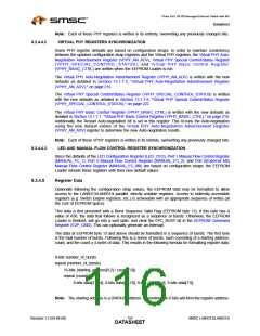
As an example, the following is a 3 burst sequence, with 1, 2, and 3 DWORDs starting at register
addresses 40h, 80h, and C0h respectively:
A5h, (Burst Sequence Valid Flag)
3h, (number_of_bursts)
16{10h, 1h}, (starting_address1 divided by 4 / count1)
11h, 12h, 13h, 14h, (4 x count1 of data)
16{20h, 2h}, (starting_address2 divided by 4 / count2)
21h, 22h, 23h, 24h, 25h, 26h, 27h, 28h, (4 x count2 of data)
16{30h, 3h}, (starting_address3 divided by 4 / count3)
31h, 32h, 33h, 34h, 35h, 36h, 37h, 38h, 39h, 3Ah, 3Bh, 3Ch (4 x count3 of data)
In order to avoid overwriting the Switch CSR register interface or the PHY Management Interface
(PMI), the EEPROM Loader waits until the CSR Busy bit of the Switch Fabric CSR Interface Command
Register (SWITCH_CSR_CMD) and the MII Busy bit of the PHY Management Interface Access
Register (PMI_ACCESS) are cleared before performing any register write.
The EEPROM Loader checks that the EEPROM address space is not exceeded. If so, it will stop and
set the EEPROM Loader Address Overflow bit in the EEPROM Command Register (E2P_CMD). The
address limit is based on the eeprom_size_strap which specifies a range of sizes. The address limit
is set to the largest value of the specified range.
8.2.4.6
8.2.4.7
EEPROM Loader Finished Wait-State
Once finished with the last burst, the EEPROM Loader will go into a wait-state and the EPC_BUSY
bit of the EEPROM Command Register (E2P_CMD) will be cleared.
Reset Sequence and EEPROM Loader
In order to allow the EEPROM Loader to change the Port 1/2 PHYs and Virtual PHY strap inputs and
maintain consistency with the PHY and Virtual PHY registers, the following sequence is used:
1. After power-up or upon
a hardware reset (nRST), the straps are sampled into the
LAN9313/LAN9313i as specified in Section 14.5.2, "Reset and Configuration Strap Timing," on
page 390.
2. After the PLL is stable, the main chip reset is released and the EEPROM Loader reads the
EEPROM and configures (overrides) the strap inputs.
3. The EEPROM Loader writes select Port 1/2 and Virtual PHY registers, as specified in
Section 8.2.4.4.1 and Section 8.2.4.4.2, respectively.
Note: Step 3 is also performed in the case of a RELOAD command or digital reset.
SMSC LAN9313/LAN9313i
117
Revision 1.2 (04-08-08)
DATASHEET

 SMSC [ SMSC CORPORATION ]